
Installation Instructions
Page 1
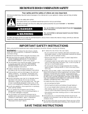
The appearance of your particular model may differ slightly from the illustration in these installation instructions. NOTES: These installation instructions cover different models. MICROWAVE HOOD COMBINATION INSTALLATION INSTRUCTIONS This product is suitable for use above electric or gas cooking products up to 36" (91.4 cm) wide.
The appearance of your particular model may differ slightly from the illustration in these installation instructions. NOTES: These installation instructions cover different models. MICROWAVE HOOD COMBINATION INSTALLATION INSTRUCTIONS This product is suitable for use above electric or gas cooking products up to 36" (91.4 cm) wide.
Installation Instructions
Page 2
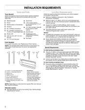
Read and follow the instructions provided with any tools listed here. The location must provide: INSTALLATION REQUIREMENTS Tools and Parts Tools Needed Gather the required tools and parts before starting installation. Location Requirements Check the opening where the microwave oven will be installed.
Read and follow the instructions provided with any tools listed here. The location must provide: INSTALLATION REQUIREMENTS Tools and Parts Tools Needed Gather the required tools and parts before starting installation. Location Requirements Check the opening where the microwave oven will be installed.
Installation Instructions
Page 3
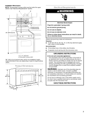
Electrical Shock Hazard Plug into a grounded 3 prong outlet. Do not use an adapter. 66" (167.6 cm) min. Observe all governing codes and ordinances. Installation Dimensions NOTE: The grounded 3 prong outlet must be inside the upper cabinet. Do not remove ground prong. See "Electrical Requirements" section. Failure to follow these instructions can result in death, fire, or electrical shock. Electrical Requirements A B WARNING 30" (76.2 cm) min. 30" (76.2 cm) typical* 12" (30.5 cm) min. 14" (35.6 cm) max. Do not use an extension cord. Required:
Electrical Shock Hazard Plug into a grounded 3 prong outlet. Do not use an adapter. 66" (167.6 cm) min. Observe all governing codes and ordinances. Installation Dimensions NOTE: The grounded 3 prong outlet must be inside the upper cabinet. Do not remove ground prong. See "Electrical Requirements" section. Failure to follow these instructions can result in death, fire, or electrical shock. Electrical Requirements A B WARNING 30" (76.2 cm) min. 30" (76.2 cm) typical* 12" (30.5 cm) min. 14" (35.6 cm) max. Do not use an extension cord. Required:
Installation Instructions
Page 4
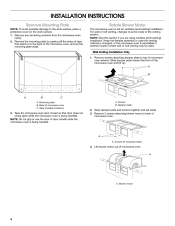
... 2 screws attaching blower motor to back of the microwave oven, and set the mounting plate aside. INSTALLATION INSTRUCTIONS Remove Mounting Plate NOTE: To avoid possible damage to the venting system. Remove the mounting plate by ...microwave oven exterior. For wall or roof venting, changes must be used. A B A B C A Screws B. Wall Venting Installation Only 1. Keep damper plate and screws together and set for ventless (recirculating) installation. Blower motor 4 A A. Rotate Blower Motor The microwave oven is being handled. A A. Back of the microwave oven and...
... 2 screws attaching blower motor to back of the microwave oven, and set the mounting plate aside. INSTALLATION INSTRUCTIONS Remove Mounting Plate NOTE: To avoid possible damage to the venting system. Remove the mounting plate by ...microwave oven exterior. For wall or roof venting, changes must be used. A B A B C A Screws B. Wall Venting Installation Only 1. Keep damper plate and screws together and set for ventless (recirculating) installation. Blower motor 4 A A. Rotate Blower Motor The microwave oven is being handled. A A. Back of the microwave oven and...
Installation Instructions
Page 5
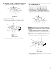
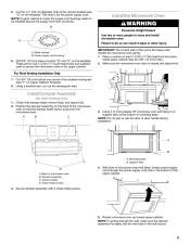
...flat sides facing the back of microwave oven. Damper plate C. A A A. A D B A. Slots D. Repeat Step 2 from "Wall Venting Installation Only." 5. Lower blower motor back into the slots in the top of the microwave oven. Make sure damper plate tabs are inserted into the ...microwave oven. 1. 2. 3. 4. 5. Make sure damper plate tabs are inserted into microwave oven. C A. Roof Venting Installation Only Repeat Step 1 from "Wall Venting Installation Only." Reattach damper plate. Screws B. Rotate blower motor 180° so that exhaust ports face the top of microwave ...
...flat sides facing the back of microwave oven. Damper plate C. A A A. A D B A. Slots D. Repeat Step 2 from "Wall Venting Installation Only." 5. Lower blower motor back into the slots in the top of the microwave oven. Make sure damper plate tabs are inserted into the ...microwave oven. 1. 2. 3. 4. 5. Make sure damper plate tabs are inserted into microwave oven. C A. Roof Venting Installation Only Repeat Step 1 from "Wall Venting Installation Only." Reattach damper plate. Screws B. Rotate blower motor 180° so that exhaust ports face the top of microwave ...
Installation Instructions
Page 6
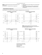
... mounting plate) B. Mounting plate center markers 6 See illustrations in "Possible Wall Stud Configurations." 1. Cabinet opening , do not install the oven. No Wall Studs at Corner Holes Figure 1 No Wall Studs at All Four Corner Holes Figure 4 A MOUNTING ...A E C F A,D A,D E C E C F A,D E C A. Mark the center of the vertical centerline (see "Mark Rear Wall" section), only recirculation or roof venting installation can be done. Wall stud centerlines D. One Wall Stud at Two Corner Holes Figure 3 Wall Studs at Corner Holes Figure 2 A MOUNTING PLATE MOUNTING PLATE A A MOUNTING...
... mounting plate) B. Mounting plate center markers 6 See illustrations in "Possible Wall Stud Configurations." 1. Cabinet opening , do not install the oven. No Wall Studs at Corner Holes Figure 1 No Wall Studs at All Four Corner Holes Figure 4 A MOUNTING ...A E C F A,D A,D E C E C F A,D E C A. Mark the center of the vertical centerline (see "Mark Rear Wall" section), only recirculation or roof venting installation can be done. Wall stud centerlines D. One Wall Stud at Two Corner Holes Figure 3 Wall Studs at Corner Holes Figure 2 A MOUNTING PLATE MOUNTING PLATE A A MOUNTING...
Installation Instructions
Page 7
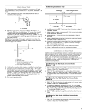
... of 1 lag screw, preferably 2 or more , hole(s) through the wall at the 2 corner holes marked in Step 3 of the cutout area. 12. Wall Venting Installation Only Centerline Upper cabinet bottom ³⁄₈" (1 cm) 4" (10.2 cm) A 6" (15.2 cm) 6" (15.2 cm) A. With the support tabs ...section. 3. See figures 1, 2 and/or 3 in "Possible Wall Stud Configurations" in "Locate Wall Stud(s)" section. 3. Installation for One Wall Stud at All Four Corner Holes (Figure 4) 1. Installation for No Wall Studs at all 4 holes are not over wall studs, use four 1/4-20 x 3" round-head bolts ...
... of 1 lag screw, preferably 2 or more , hole(s) through the wall at the 2 corner holes marked in Step 3 of the cutout area. 12. Wall Venting Installation Only Centerline Upper cabinet bottom ³⁄₈" (1 cm) 4" (10.2 cm) A 6" (15.2 cm) 6" (15.2 cm) A. With the support tabs ...section. 3. See figures 1, 2 and/or 3 in "Possible Wall Stud Configurations" in "Locate Wall Stud(s)" section. 3. Installation for One Wall Stud at All Four Corner Holes (Figure 4) 1. Installation for No Wall Studs at all 4 holes are not over wall studs, use four 1/4-20 x 3" round-head bolts ...
Installation Instructions
Page 8
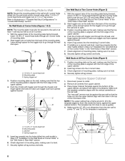
... the 4 bolts with the front edge of the microwave oven. Position mounting plate on the template is maintained. 3. Check alignment of "Installation for the toggle nuts to go through the drywall, and finger tighten the bolts to make sure toggle nuts have opened against the rear wall...2 lag screws into the wall studs and/or drywall using either 1/4-20 x 3" round-head bolts and toggle nuts or 1/4 x 2" lag screws. If installing on at Corner Holes" in the "Drill Holes in Step 2 of the mounting plate. Check alignment of the upper cabinet. 4. Securely tighten all contents from...
... the 4 bolts with the front edge of the microwave oven. Position mounting plate on the template is maintained. 3. Check alignment of "Installation for the toggle nuts to go through the drywall, and finger tighten the bolts to make sure toggle nuts have opened against the rear wall...2 lag screws into the wall studs and/or drywall using either 1/4-20 x 3" round-head bolts and toggle nuts or 1/4 x 2" lag screws. If installing on at Corner Holes" in the "Drill Holes in Step 2 of the mounting plate. Check alignment of the upper cabinet. 4. Securely tighten all contents from...
Installation Instructions
Page 9
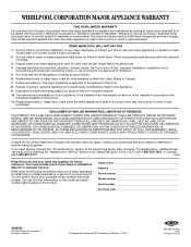
...blade moves freely, and opens fully. 2. Sheet metal screws 4. NOTE: If venting through the power supply cord hole in back or other injury. Install the Microwave Oven B WARNING Excessive Weight Hazard Use two or more people, lift microwave oven and hang it on Upper Cabinet Template. 8. A A.... Position the damper assembly on the template. NOTE: Do not grip or use the door or door handle during installation. Cut the 1¹⁄₂" (3.8 cm) diameter hole at points "D" and "E" on each 1/4-20 x 3" flat-head bolt and place inside upper ...
...blade moves freely, and opens fully. 2. Sheet metal screws 4. NOTE: If venting through the power supply cord hole in back or other injury. Install the Microwave Oven B WARNING Excessive Weight Hazard Use two or more people, lift microwave oven and hang it on Upper Cabinet Template. 8. A A.... Position the damper assembly on the template. NOTE: Do not grip or use the door or door handle during installation. Cut the 1¹⁄₂" (3.8 cm) diameter hole at points "D" and "E" on each 1/4-20 x 3" flat-head bolt and place inside upper ...
Installation Instructions
Page 12
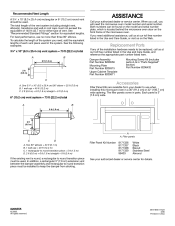
The filler panels come in China If you will need , add the equivalent lengths of the installation hardware needs to round transition piece must be used . Two 90° elbows = 20 ft (6.1 m) B. 1 wall cap = 40 ft (12.2 m) C. 1 rectangular to round transition piece = 5 ... oven model number and serial number. The total length of the vent system including straight vent, elbow(s), transitions and wall or roof caps must be installed to use no more than three 90° elbows. To calculate the length of vent. For best performance, use when...
The filler panels come in China If you will need , add the equivalent lengths of the installation hardware needs to round transition piece must be used . Two 90° elbows = 20 ft (6.1 m) B. 1 wall cap = 40 ft (12.2 m) C. 1 rectangular to round transition piece = 5 ... oven model number and serial number. The total length of the vent system including straight vent, elbow(s), transitions and wall or roof caps must be installed to use no more than three 90° elbows. To calculate the length of vent. For best performance, use when...
Use and Care Guide
Page 3
...or if it . - Do not overheat the liquid. - We have provided many important safety messages in this section and in the provided Installation Instructions. ■ Install or locate the microwave oven only in the oven cavity: - This is specifically designed to excessive microwave energy: ■ Read all safety ...be inserted in the microwave oven as they may create a fire or risk of electric shock. ■ Do not clean with the provided Installation Instructions. ■ Some products such as whole eggs in the microwave oven. ■ Use the microwave oven only for its intended use ...
...or if it . - Do not overheat the liquid. - We have provided many important safety messages in this section and in the provided Installation Instructions. ■ Install or locate the microwave oven only in the oven cavity: - This is specifically designed to excessive microwave energy: ■ Read all safety ...be inserted in the microwave oven as they may create a fire or risk of electric shock. ■ Do not clean with the provided Installation Instructions. ■ Some products such as whole eggs in the microwave oven. ■ Use the microwave oven only for its intended use ...

Use and Care Guide
Page 4
...Plug into an outlet that there is no damage to whether the microwave oven is too short, have a qualified electrician or serviceman install an outlet near water - Observe all cord connected appliances: The microwave oven must be grounded. WARNING: Improper use paper products when appliance... is properly installed and grounded. SAVE THESE INSTRUCTIONS This device complies with the door open since open-door operation can result in harmful exposure to ...
...Plug into an outlet that there is no damage to whether the microwave oven is too short, have a qualified electrician or serviceman install an outlet near water - Observe all cord connected appliances: The microwave oven must be grounded. WARNING: Improper use paper products when appliance... is properly installed and grounded. SAVE THESE INSTRUCTIONS This device complies with the door open since open-door operation can result in harmful exposure to ...

Use and Care Guide
Page 5
... manual may differ slightly from the illustrations in this microwave oven. ■ Clean rack supports often (see "General Cleaning" section). Cooking rack E. Cooktop light K. To Install: 1. Always use oven mitts or pot holders when handling. ■ Do not allow the rack to touch the inside the turntable bottom ridge. ■ When...
... manual may differ slightly from the illustrations in this microwave oven. ■ Clean rack supports often (see "General Cleaning" section). Cooking rack E. Cooktop light K. To Install: 1. Always use oven mitts or pot holders when handling. ■ Do not allow the rack to touch the inside the turntable bottom ridge. ■ When...

Use and Care Guide
Page 15
... grille forward and down until the filter drops out. 2. A A. Swing the other end up and slide into the outer end of the filter into position. Install new charcoal filter. 5. Replacing Cooktop Light The cooktop light is a candelabra base bulb. Remove the bulb cover mounting screw. Remove each grease filter by inserting...
... grille forward and down until the filter drops out. 2. A A. Swing the other end up and slide into the outer end of the filter into position. Install new charcoal filter. 5. Replacing Cooktop Light The cooktop light is a candelabra base bulb. Remove the bulb cover mounting screw. Remove each grease filter by inserting...

Use and Care Guide
Page 16
... to the inside of an unnecessary service call for 2 minutes at 100% cooking power. Firmly close door. ■ Is the electronic oven control set ? See Installation Instructions provided with your microwave oven. See "Assistance or Service" section. Replacing Microwave Oven Light The microwave oven light is normal and will not affect...
... to the inside of an unnecessary service call for 2 minutes at 100% cooking power. Firmly close door. ■ Is the electronic oven control set ? See Installation Instructions provided with your microwave oven. See "Assistance or Service" section. Replacing Microwave Oven Light The microwave oven light is normal and will not affect...

Use and Care Guide
Page 18
... FSP® replacement parts in your area, call . Whirlpool designated service technicians are made with the same precision used to build every new WHIRLPOOL® appliance. It may save you the cost of appliances. ■ Installation information. ■ Use and maintenance procedures. ■ ... need further assistance, you use only FSP® replacement parts. Our consultants provide assistance with any questions or concerns at: Whirlpool Brand Home Appliances Customer eXperience Center 553 Benson Road Benton Harbor, MI 49022-2692 Please include a daytime phone number in the...
... FSP® replacement parts in your area, call . Whirlpool designated service technicians are made with the same precision used to build every new WHIRLPOOL® appliance. It may save you the cost of appliances. ■ Installation information. ■ Use and maintenance procedures. ■ ... need further assistance, you use only FSP® replacement parts. Our consultants provide assistance with any questions or concerns at: Whirlpool Brand Home Appliances Customer eXperience Center 553 Benson Road Benton Harbor, MI 49022-2692 Please include a daytime phone number in the...
Use and Care Guide
Page 20
...on the product. DISCLAIMER OF IMPLIED WARRANTIES; WHIRLPOOL CORPORATION MAJOR APPLIANCE WARRANTY ONE YEAR LIMITED WARRANTY For one year from accident, alteration, misuse, abuse, fire, flood, acts of God, improper installation, installation not in accordance with electrical or plumbing codes,... or use of products not approved by Whirlpool. 5. Repairs when your authorized Whirlpool dealer to better help can find this warranty does not apply...
...on the product. DISCLAIMER OF IMPLIED WARRANTIES; WHIRLPOOL CORPORATION MAJOR APPLIANCE WARRANTY ONE YEAR LIMITED WARRANTY For one year from accident, alteration, misuse, abuse, fire, flood, acts of God, improper installation, installation not in accordance with electrical or plumbing codes,... or use of products not approved by Whirlpool. 5. Repairs when your authorized Whirlpool dealer to better help can find this warranty does not apply...

Dimensions
Page 1
...35.6 cm) cabinet depth recommended NOTE: There must be installed together. wall cap 8 feet straight = 5 ft. (1.5 m) = 20 ft. (6.1 m) = 40 ft. (12.2 m) = 8 ft. (2.4 m) Length of 6" system = 73 ft. (22.2 m) A Because Whirlpool Corporation policy includes a continuous commitment to change materials and .... wall cap = 40 ft. (12.2 m) 8 feet straight = 8 ft. (2.4 m) Length of rigid metal vent. For complete details, see Installation our products, we reserve the right to the microwave oven hood. We do NOT recommend: ✔ flexible metal vent. See examples below. 3-1/4" x...
...35.6 cm) cabinet depth recommended NOTE: There must be installed together. wall cap 8 feet straight = 5 ft. (1.5 m) = 20 ft. (6.1 m) = 40 ft. (12.2 m) = 8 ft. (2.4 m) Length of 6" system = 73 ft. (22.2 m) A Because Whirlpool Corporation policy includes a continuous commitment to change materials and .... wall cap = 40 ft. (12.2 m) 8 feet straight = 8 ft. (2.4 m) Length of rigid metal vent. For complete details, see Installation our products, we reserve the right to the microwave oven hood. We do NOT recommend: ✔ flexible metal vent. See examples below. 3-1/4" x...
Parts Guide
Page 7
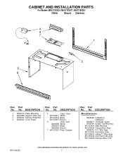
... 1 8206315 Plate, Mounting 2 8206385 Support, Wire Clip 3 8206442 Damper Assembly 4 8206442 Cord, Power Illus. No. DESCRIPTION Miscellaneous 8205948 Installation, Hardware 8205871 Template, Upper 8169704 Screw, Top Mountng W10163434 Main Harness W10163438 Ground Wire Assy 8206415 H.V. No. No. Wire Assy W10107760 ...Black W10163419 Biscuit 6 Grille, Vent 8206390 White 8206391 Black 8206392 Biscuit 7 W10157207 Plate, Damper Illus. Part No. Part No. CABINET AND INSTALLATION PARTS For Models: MH2175XSQ1, MH2175XST1, MH2175XSS1 (White) (Biscuit) (Stainless) Illus. Part No.
... 1 8206315 Plate, Mounting 2 8206385 Support, Wire Clip 3 8206442 Damper Assembly 4 8206442 Cord, Power Illus. No. DESCRIPTION Miscellaneous 8205948 Installation, Hardware 8205871 Template, Upper 8169704 Screw, Top Mountng W10163434 Main Harness W10163438 Ground Wire Assy 8206415 H.V. No. No. Wire Assy W10107760 ...Black W10163419 Biscuit 6 Grille, Vent 8206390 White 8206391 Black 8206392 Biscuit 7 W10157207 Plate, Damper Illus. Part No. Part No. CABINET AND INSTALLATION PARTS For Models: MH2175XSQ1, MH2175XST1, MH2175XSS1 (White) (Biscuit) (Stainless) Illus. Part No.


