
Installation Instructions
Page 1
NOTES: MICROWAVE HOOD COMBINATION INSTALLATION INSTRUCTIONS This product is suitable for use above electric or gas cooking products up to 36" (91.4 cm) wide. These installation instructions cover different models. The appearance of your particular model may differ slightly from the illustration in these installation instructions.
NOTES: MICROWAVE HOOD COMBINATION INSTALLATION INSTRUCTIONS This product is suitable for use above electric or gas cooking products up to 36" (91.4 cm) wide. These installation instructions cover different models. The appearance of your particular model may differ slightly from the illustration in these installation instructions.
Installation Instructions
Page 2
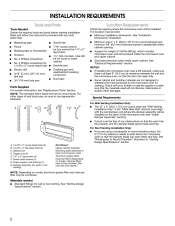
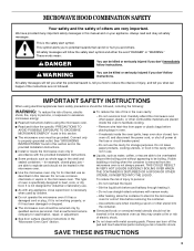
INSTALLATION REQUIREMENTS Tools and Parts Tools Needed Gather the required tools and parts before starting installation. The location must provide: Location Requirements Check the opening where the microwave oven will be installed. Read and follow the instructions provided with any tools listed here.
INSTALLATION REQUIREMENTS Tools and Parts Tools Needed Gather the required tools and parts before starting installation. The location must provide: Location Requirements Check the opening where the microwave oven will be installed. Read and follow the instructions provided with any tools listed here.
Installation Instructions
Page 3
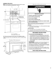
Electrical Shock Hazard Plug into a grounded 3 prong outlet. Failure to follow these instructions can result in death, fire, or electrical shock. Required: See "Electrical Requirements" section. Observe all governing codes and ordinances. Do not remove ground prong. Do not use an extension cord. Do not use an adapter. 66" (167.6 cm) min. Electrical Requirements A B WARNING 30" (76.2 cm) min. 30" (76.2 cm) typical* 12" (30.5 cm) min. 14" (35.6 cm) max. Installation Dimensions NOTE: The grounded 3 prong outlet must be inside the upper cabinet.
Electrical Shock Hazard Plug into a grounded 3 prong outlet. Failure to follow these instructions can result in death, fire, or electrical shock. Required: See "Electrical Requirements" section. Observe all governing codes and ordinances. Do not remove ground prong. Do not use an extension cord. Do not use an adapter. 66" (167.6 cm) min. Electrical Requirements A B WARNING 30" (76.2 cm) min. 30" (76.2 cm) typical* 12" (30.5 cm) min. 14" (35.6 cm) max. Installation Dimensions NOTE: The grounded 3 prong outlet must be inside the upper cabinet.
Installation Instructions
Page 4
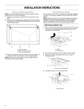
...Do not grip or use the door or door handle while the microwave oven is reinstalled in recessed holes) 4. Blower motor 4 INSTALLATION INSTRUCTIONS Remove Mounting Plate NOTE: To avoid possible damage to the venting system. Screws (in another location where wall or roof ...the work surface, place a protective cover on the work surface. 1. A A. NOTE: Skip this section if you are using ventless (recirculating) installation. Remove any remaining contents from the microwave oven cavity. 2. Remove the mounting plate by peeling off the strips of microwave oven exterior. Tape (multiple...
...Do not grip or use the door or door handle while the microwave oven is reinstalled in recessed holes) 4. Blower motor 4 INSTALLATION INSTRUCTIONS Remove Mounting Plate NOTE: To avoid possible damage to the venting system. Screws (in another location where wall or roof ...the work surface, place a protective cover on the work surface. 1. A A. NOTE: Skip this section if you are using ventless (recirculating) installation. Remove any remaining contents from the microwave oven cavity. 2. Remove the mounting plate by peeling off the strips of microwave oven exterior. Tape (multiple...
Installation Instructions
Page 5
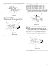
... port C A. Reattach blower motor to the microwave oven. 7. Make sure damper plate tabs are inserted into the slots in Step 3 of "Wall Venting Installation Only." A A A. Reattach damper plate. Securely tighten screws. Reattach damper plate. A D B 8. Screws B. Damper plate tabs 8. Rotate blower motor ... the slots in the top of microwave oven with 2 screws removed in Step 1. Damper plate C. Repeat Step 3 from "Wall Venting Installation Only." A D B A. NOTE: If blower motor is not positioned with flat sides facing the back of the microwave oven (as ...
... port C A. Reattach blower motor to the microwave oven. 7. Make sure damper plate tabs are inserted into the slots in Step 3 of "Wall Venting Installation Only." A A A. Reattach damper plate. Securely tighten screws. Reattach damper plate. A D B 8. Screws B. Damper plate tabs 8. Rotate blower motor ... the slots in the top of microwave oven with 2 screws removed in Step 1. Damper plate C. Repeat Step 3 from "Wall Venting Installation Only." A D B A. NOTE: If blower motor is not positioned with flat sides facing the back of the microwave oven (as ...
Installation Instructions
Page 6
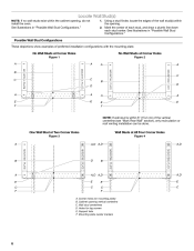
... (see "Mark Rear Wall" section), only recirculation or roof venting installation can be done. See illustrations in "Possible Wall Stud Configurations." 1. Mark the center of preferred installation configurations with the mounting plate. Mounting plate center markers 6 Cabinet opening... A E B A E F A E F A E NOTE: If wall stud is within 6" (15.2 cm) of the wall stud(s) within the cabinet opening, do not install the oven. No Wall Studs at Corner Holes Figure 1 No Wall Studs at All Four Corner Holes Figure 4 A MOUNTING PLATE MOUNTING PLATE A,D A,D MOUNTING PLATE MOUNTING...
... (see "Mark Rear Wall" section), only recirculation or roof venting installation can be done. See illustrations in "Possible Wall Stud Configurations." 1. Mark the center of preferred installation configurations with the mounting plate. Mounting plate center markers 6 Cabinet opening... A E B A E F A E F A E NOTE: If wall stud is within 6" (15.2 cm) of the wall stud(s) within the cabinet opening, do not install the oven. No Wall Studs at Corner Holes Figure 1 No Wall Studs at All Four Corner Holes Figure 4 A MOUNTING PLATE MOUNTING PLATE A,D A,D MOUNTING PLATE MOUNTING...
Installation Instructions
Page 7
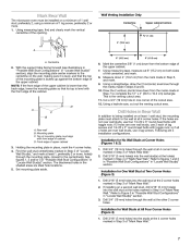
...the upper cabinet. Using a straightedge, draw the 2 horizontal, level lines through the wall at all 4 corner holes. Top of mounting plate must be installed on a minimum of 1 wall stud, preferably 2, using a minimum of 1 lag screw, preferably 2 or more , hole(s) through the wall at ...on at least 1 wall stud, the mounting plate must attach to Figure 3 in "Possible Wall Stud Configurations" in Step 4 of "Mark Rear Wall." Wall Venting Installation Only Centerline Upper cabinet bottom ³⁄₈" (1 cm) 4" (10.2 cm) A 6" (15.2 cm) 6" (15.2 cm) A. Centerline 2. Using ...
...the upper cabinet. Using a straightedge, draw the 2 horizontal, level lines through the wall at all 4 corner holes. Top of mounting plate must be installed on a minimum of 1 wall stud, preferably 2, using a minimum of 1 lag screw, preferably 2 or more , hole(s) through the wall at ...on at least 1 wall stud, the mounting plate must attach to Figure 3 in "Possible Wall Stud Configurations" in Step 4 of "Mark Rear Wall." Wall Venting Installation Only Centerline Upper cabinet bottom ³⁄₈" (1 cm) 4" (10.2 cm) A 6" (15.2 cm) 6" (15.2 cm) A. Centerline 2. Using ...
Installation Instructions
Page 8
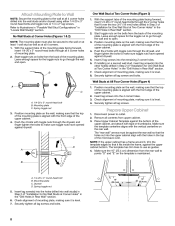
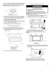
... forward, insert 1/4-20 x 3" round-head bolts through the drywall, and finger tighten the bolts to make sure toggle nuts have opened against the bottom of "Installation for the toggle nut to go through the wall and to open . Push the 2 bolts with toggle nuts through the 2 corner holes that the top... mounting plate must be secured to the wall on the wall, making sure that fit over the two 3/4" (19 mm) holes drilled in Step 2 of "Installation for One Wall Stud at Two Corner Holes" in the "Drill Holes in Rear Wall" section. 6. Leave enough space for the toggle nuts to go...
... forward, insert 1/4-20 x 3" round-head bolts through the drywall, and finger tighten the bolts to make sure toggle nuts have opened against the bottom of "Installation for the toggle nut to go through the wall and to open . Push the 2 bolts with toggle nuts through the 2 corner holes that the top... mounting plate must be secured to the wall on the wall, making sure that fit over the two 3/4" (19 mm) holes drilled in Step 2 of "Installation for One Wall Stud at Two Corner Holes" in the "Drill Holes in Rear Wall" section. 6. Leave enough space for the toggle nuts to go...
Installation Instructions
Page 9
... support tabs at one corner of microwave oven B. A B C 3. NOTE: Do not grip or use the door or door handle during installation. Mounting plate B. Damper blade D. With front of microwave oven still tilted, thread power supply cord through the wall, make sure the damper...a keyhole saw, cut out the rectangular area. Position the damper assembly on Upper Cabinet Template. 8. Damper assembly C. Sheet metal screws 4. Failure to be installed around the supply cord hole, as shown. Metal cabinet B. Cut 3/4" (19 mm) hole at the bottom of the upper cabinet. 3. A B A....
... support tabs at one corner of microwave oven B. A B C 3. NOTE: Do not grip or use the door or door handle during installation. Mounting plate B. Damper blade D. With front of microwave oven still tilted, thread power supply cord through the wall, make sure the damper...a keyhole saw, cut out the rectangular area. Position the damper assembly on Upper Cabinet Template. 8. Damper assembly C. Sheet metal screws 4. Failure to be installed around the supply cord hole, as shown. Metal cabinet B. Cut 3/4" (19 mm) hole at the bottom of the upper cabinet. 3. A B A....
Installation Instructions
Page 12
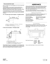
...at our toll free number listed in a 36" (91.4 cm) or 42" (106.7 cm) wide opening. For best performance, use when installing this microwave oven in the Use and Care Guide, and reference the appropriate part number listed here. See the following examples: ASSISTANCE Call your dealer... the equivalent of 140 ft (42.7 m) for either type of the vent system including straight vent, elbow(s), transitions and wall or roof caps must be installed to round transition piece must be used in "Parts Supplied" section) Part Number 8206432 3¹⁄₄" x 10" (8.3 x 25.4 cm) vent ...
...at our toll free number listed in a 36" (91.4 cm) or 42" (106.7 cm) wide opening. For best performance, use when installing this microwave oven in the Use and Care Guide, and reference the appropriate part number listed here. See the following examples: ASSISTANCE Call your dealer... the equivalent of 140 ft (42.7 m) for either type of the vent system including straight vent, elbow(s), transitions and wall or roof caps must be installed to round transition piece must be used in "Parts Supplied" section) Part Number 8206432 3¹⁄₄" x 10" (8.3 x 25.4 cm) vent ...
Use and Care Guide
Page 3
...risk of fire in oven. - Connect only to persons: - Do not use corrosive chemicals or vapors in use . ■ As with the provided Installation Instructions. ■ Some products such as they may create a fire or risk of electric shock. ■ Do not clean with narrow necks. -... an authorized service company for industrial or laboratory use . ■ Liquids, such as described in this section and in the provided Installation Instructions. ■ Install or locate the microwave oven only in this section. ■ The microwave oven must be killed or seriously injured if you what ...
...risk of fire in oven. - Connect only to persons: - Do not use corrosive chemicals or vapors in use . ■ As with the provided Installation Instructions. ■ Some products such as they may create a fire or risk of electric shock. ■ Do not clean with narrow necks. -... an authorized service company for industrial or laboratory use . ■ Liquids, such as described in this section and in the provided Installation Instructions. ■ Install or locate the microwave oven only in this section. ■ The microwave oven must be killed or seriously injured if you what ...

Use and Care Guide
Page 4
... Electrical Shock Hazard Plug into an outlet that there is damaged. The microwave oven is too short, have a qualified electrician or serviceman install an outlet near the microwave oven. This will cause overheating of the FCC Rules. 4 SAVE THESE INSTRUCTIONS PRECAUTIONS TO AVOID POSSIBLE EXPOSURE TO... should not be used above both gas and electric cooking equipment. ■ Intended to be allowed to whether the microwave oven is properly installed and grounded. Do not use an extension cord. It is important not to defeat or tamper with the safety interlocks. (b) Do not ...
... Electrical Shock Hazard Plug into an outlet that there is damaged. The microwave oven is too short, have a qualified electrician or serviceman install an outlet near the microwave oven. This will cause overheating of the FCC Rules. 4 SAVE THESE INSTRUCTIONS PRECAUTIONS TO AVOID POSSIBLE EXPOSURE TO... should not be used above both gas and electric cooking equipment. ■ Intended to be allowed to whether the microwave oven is properly installed and grounded. Do not use an extension cord. It is important not to defeat or tamper with the safety interlocks. (b) Do not ...

Use and Care Guide
Page 5
... the support. Fit the raised, curved lines in oven cavity) J. This is designed specifically for cooking, remove it on the rack. Microwave oven light F. To Install: 1. Microwave inlet cover L. A "turntable off for two-level cooking. Do not operate the oven without having the turntable in this microwave oven.
... the support. Fit the raised, curved lines in oven cavity) J. This is designed specifically for cooking, remove it on the rack. Microwave oven light F. To Install: 1. Microwave inlet cover L. A "turntable off for two-level cooking. Do not operate the oven without having the turntable in this microwave oven.

Use and Care Guide
Page 15
To Remove and Replace Grease Filters: 1. Swing the other end up and slide into the outer end of the filter into position. Install new charcoal filter. 5. Replacing Cooktop Light The cooktop light is a candelabra base bulb. Replace mounting screw. 4. Do not operate the microwave oven or exhaust fan ...
To Remove and Replace Grease Filters: 1. Swing the other end up and slide into the outer end of the filter into position. Install new charcoal filter. 5. Replacing Cooktop Light The cooktop light is a candelabra base bulb. Replace mounting screw. 4. Do not operate the microwave oven or exhaust fan ...

Use and Care Guide
Page 16
...) attached to heat 1 cup (250 mL) of water on and off. See "Assistance or Service" section. Unplug microwave oven or disconnect power. 2. Replace light. See Installation Instructions provided with your microwave oven. Remove spacer, then firmly close door. ■ Is a spacer (on some models, is normal and occurs when the power...
...) attached to heat 1 cup (250 mL) of water on and off. See "Assistance or Service" section. Unplug microwave oven or disconnect power. 2. Replace light. See Installation Instructions provided with your microwave oven. Remove spacer, then firmly close door. ■ Is a spacer (on some models, is normal and occurs when the power...

Use and Care Guide
Page 18
... If you need to order replacement parts, we recommend that you still need further assistance, you can write to Whirlpool Corporation with : ■ Features and specifications on our full line of appliances. ■ Installation information. ■ Use and maintenance procedures. ■ Accessory and repair parts sales. ■ Specialized customer assistance (Spanish speaking...
... If you need to order replacement parts, we recommend that you still need further assistance, you can write to Whirlpool Corporation with : ■ Features and specifications on our full line of appliances. ■ Installation information. ■ Use and maintenance procedures. ■ Accessory and repair parts sales. ■ Specialized customer assistance (Spanish speaking...
Use and Care Guide
Page 20
... appliance is operated and maintained according to instructions attached to or furnished with published installation instructions. 11. This limited warranty applies only when the major appliance is not installed in accordance with the product, Whirlpool Corporation or Whirlpool Canada LP (hereafter "Whirlpool") will need service, first see the "Troubleshooting" section of the Use & Care Guide...
... appliance is operated and maintained according to instructions attached to or furnished with published installation instructions. 11. This limited warranty applies only when the major appliance is not installed in accordance with the product, Whirlpool Corporation or Whirlpool Canada LP (hereafter "Whirlpool") will need service, first see the "Troubleshooting" section of the Use & Care Guide...

Dimensions
Page 1
... straight vent, elbow, transitions, wall or roof caps must not exceed the equivalent of 140 feet (42.7 m) for the exhaust vent. For complete details, see Installation our products, we reserve the right to 6" = 5 ft. 3-1/4" x 10" 3-1/4" x 10" roof cap = 24 ft. 90° elbow = 25 ft. 90&#... must exist between cabinets must be 30" (76.2 cm) minimum and be free of 6" system = 73 ft. (22.2 m) A Because Whirlpool Corporation policy includes a continuous commitment to 35.6 cm) cabinet depth recommended NOTE: There must be used in the upper cabinet as close as standard elbows...
... straight vent, elbow, transitions, wall or roof caps must not exceed the equivalent of 140 feet (42.7 m) for the exhaust vent. For complete details, see Installation our products, we reserve the right to 6" = 5 ft. 3-1/4" x 10" 3-1/4" x 10" roof cap = 24 ft. 90° elbow = 25 ft. 90&#... must exist between cabinets must be 30" (76.2 cm) minimum and be free of 6" system = 73 ft. (22.2 m) A Because Whirlpool Corporation policy includes a continuous commitment to 35.6 cm) cabinet depth recommended NOTE: There must be used in the upper cabinet as close as standard elbows...
Parts Guide
Page 7
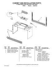
...1 8206315 Plate, Mounting 2 8206385 Support, Wire Clip 3 8206442 Damper Assembly 4 8206442 Cord, Power Illus. Part No. CABINET AND INSTALLATION PARTS For Models: MH2175XSQ1, MH2175XST1, MH2175XSS1 (White) (Biscuit) (Stainless) Illus. No. No. No. Wire Assy W10107760 Grnd Wire,...W10163418 Black W10163419 Biscuit 6 Grille, Vent 8206390 White 8206391 Black 8206392 Biscuit 7 W10157207 Plate, Damper Illus. DESCRIPTION Miscellaneous 8205948 Installation, Hardware 8205871 Template, Upper 8169704 Screw, Top Mountng W10163434 Main Harness W10163438 Ground Wire Assy 8206415 H.V. Part No.
...1 8206315 Plate, Mounting 2 8206385 Support, Wire Clip 3 8206442 Damper Assembly 4 8206442 Cord, Power Illus. Part No. CABINET AND INSTALLATION PARTS For Models: MH2175XSQ1, MH2175XST1, MH2175XSS1 (White) (Biscuit) (Stainless) Illus. No. No. No. Wire Assy W10107760 Grnd Wire,...W10163418 Black W10163419 Biscuit 6 Grille, Vent 8206390 White 8206391 Black 8206392 Biscuit 7 W10157207 Plate, Damper Illus. DESCRIPTION Miscellaneous 8205948 Installation, Hardware 8205871 Template, Upper 8169704 Screw, Top Mountng W10163434 Main Harness W10163438 Ground Wire Assy 8206415 H.V. Part No.


