
Owners Manual
Page 5
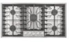
HI HI HI HI HI LO 36" (91.4 cm) model Control Panel A B C D E F LO LO LO LO Cooktop A. Center control knob E. Surface burner cap and head 5 Left front control knob A D. Surface burner grate B. Control panel C. Right rear control knob C B A. Right front control knob F. Left rear control knob B. Surface burner locator C.
HI HI HI HI HI LO 36" (91.4 cm) model Control Panel A B C D E F LO LO LO LO Cooktop A. Center control knob E. Surface burner cap and head 5 Left front control knob A D. Surface burner grate B. Control panel C. Right rear control knob C B A. Right front control knob F. Left rear control knob B. Surface burner locator C.
Dimension Guide
Page 1
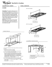
...Gas shutoff valve Because Whirlpool Corporation policy includes a continuous commitment to LP gas. Ref. 9761893 12-13-05 Pipe-joint compounds that a separate circuit serving only this cooktop be converted to improve Dimensions are for use TEFLON® tape. Cooktop can be used in insufficient gas supply. Usually, LP gas...GLS3064R GLS3665R Gas Supply: This cooktop is factory set for planning purposes only. Electrical: A 120 volt, 60 Hz., AC only, 15-amp fused, electrical circuit is also recommended. Cabinet C. 30" (76.2 cm) on 30" (76.2 cm) models 36" (91.4 cm) on 36" ...
...Gas shutoff valve Because Whirlpool Corporation policy includes a continuous commitment to LP gas. Ref. 9761893 12-13-05 Pipe-joint compounds that a separate circuit serving only this cooktop be converted to improve Dimensions are for use TEFLON® tape. Cooktop can be used in insufficient gas supply. Usually, LP gas...GLS3064R GLS3665R Gas Supply: This cooktop is factory set for planning purposes only. Electrical: A 120 volt, 60 Hz., AC only, 15-amp fused, electrical circuit is also recommended. Cabinet C. 30" (76.2 cm) on 30" (76.2 cm) models 36" (91.4 cm) on 36" ...
Installation Instructions
Page 1
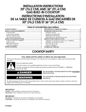
...You can be killed or seriously injured if you don't immediately follow instructions. INSTALLATION INSTRUCTIONS 30" (76.2 CM) AND 36" (91.4 CM) GAS BUILT-IN COOKTOP INSTRUCTIONS D'INSTALLATION DE LA TABLE DE CUISSON À GAZ ENCASTRÉE DE 30" (76,2 CM) ET... 36" (91,4 CM) Table of Contents/Table des matières COOKTOP SAFETY 1 SÉCURITÉ DE LA TABLE DE CUISSON 9 INSTALLATION REQUIREMENTS 2 Tools and Parts 2 Location Requirements 2 Electrical Requirements 4 Gas Supply Requirements 4 EXIGENCES D'INSTALLATION 10 Outillage et pi&#...
...You can be killed or seriously injured if you don't immediately follow instructions. INSTALLATION INSTRUCTIONS 30" (76.2 CM) AND 36" (91.4 CM) GAS BUILT-IN COOKTOP INSTRUCTIONS D'INSTALLATION DE LA TABLE DE CUISSON À GAZ ENCASTRÉE DE 30" (76,2 CM) ET... 36" (91,4 CM) Table of Contents/Table des matières COOKTOP SAFETY 1 SÉCURITÉ DE LA TABLE DE CUISSON 9 INSTALLATION REQUIREMENTS 2 Tools and Parts 2 Location Requirements 2 Electrical Requirements 4 Gas Supply Requirements 4 EXIGENCES D'INSTALLATION 10 Outillage et pi&#...
Installation Instructions
Page 3
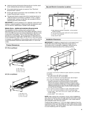
..., or with local codes. In Canada, the installation of the cooktop. See "Gas Supply Requirements" section. ■ The gas and electric supply should be shortened to clear the burner box. D A B C F C B A. 30" (76.2 cm) B. 20¹⁄₈" (51.1 cm) C. 2 7.2 cm) 36" (91.4 cm) Model A C B A. 36" (91.4 cm) B. 20¹⁄₈" (51.1 cm) C. 2 7.2 cm) J A I . arrow...
..., or with local codes. In Canada, the installation of the cooktop. See "Gas Supply Requirements" section. ■ The gas and electric supply should be shortened to clear the burner box. D A B C F C B A. 30" (76.2 cm) B. 20¹⁄₈" (51.1 cm) C. 2 7.2 cm) 36" (91.4 cm) Model A C B A. 36" (91.4 cm) B. 20¹⁄₈" (51.1 cm) C. 2 7.2 cm) J A I . arrow...
Installation Instructions
Page 4
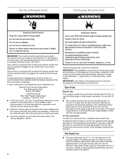
...box has information on longer runs may result in the package containing the literature. If connected to the cooktop location. A smaller size pipe on the types of Gas Natural Gas: This cooktop is listed by a qualified service technician. In the absence of ¾" (1.9 cm) rigid pipe ...to LP, have a qualified person make sure gas pressure does not exceed 14" (36 cm) water column. Gas Supply Line ■ Provide a gas supply line of local...
...box has information on longer runs may result in the package containing the literature. If connected to the cooktop location. A smaller size pipe on the types of Gas Natural Gas: This cooktop is listed by a qualified service technician. In the absence of ¾" (1.9 cm) rigid pipe ...to LP, have a qualified person make sure gas pressure does not exceed 14" (36 cm) water column. Gas Supply Line ■ Provide a gas supply line of local...
Installation Instructions
Page 6
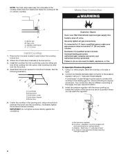
... the other end into the cutout. 4. Connect the flexible stainless steel connector to the existing gas line. A combination of pipe fittings must be used to connect the cooktop to the pressure regulator using a wood block between the screw and the countertop, moderately tighten ...the screws to the supply line type, size and location. 3. Shown following illustration. Must have a qualified person make sure gas pressure does not exceed 14" (36 cm) water column. A B Make Gas ...
... the other end into the cutout. 4. Connect the flexible stainless steel connector to the existing gas line. A combination of pipe fittings must be used to connect the cooktop to the pressure regulator using a wood block between the screw and the countertop, moderately tighten ...the screws to the supply line type, size and location. 3. Shown following illustration. Must have a qualified person make sure gas pressure does not exceed 14" (36 cm) water column. A B Make Gas ...
Installation Instructions
Page 8
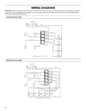
... 18 BU # 15 18 BU # 17 N #1 L1 18 W # 12 18 BU # 18 SPARK MODULE WIRING DIAGRAM 30" (76.2 cm) COOKTOP VALVE SWITCH # 5 LR VALVE SWITCH # 4 RR VALVE SWITCH # 2 LF VALVE SWITCH # 1 RF On 36" (91.4 cm) models 18 G # 3 18 BK # 1 POWER SUPPLY N G L1 N L1 18 W # 2 18 W # 9 18 BK # 4 # 1 IGNITER # 2 ...18 BK # 8 B VALVE SWITCH # 2 A LF 18 BK # 7 VALVE B SWITCH # 3 A CENTER 18 BK # 6 VALVE B SWITCH # 4 A RF 18 BK # 5 VALVE B SWITCH # 5 A RR 18 BK # 4 WIRING DIAGRAM 36" (91.4 cm) COOKTOP 8 WIRING DIAGRAMS CAUTION: Label all wires prior to disconnection when servicing controls.
... 18 BU # 15 18 BU # 17 N #1 L1 18 W # 12 18 BU # 18 SPARK MODULE WIRING DIAGRAM 30" (76.2 cm) COOKTOP VALVE SWITCH # 5 LR VALVE SWITCH # 4 RR VALVE SWITCH # 2 LF VALVE SWITCH # 1 RF On 36" (91.4 cm) models 18 G # 3 18 BK # 1 POWER SUPPLY N G L1 N L1 18 W # 2 18 W # 9 18 BK # 4 # 1 IGNITER # 2 ...18 BK # 8 B VALVE SWITCH # 2 A LF 18 BK # 7 VALVE B SWITCH # 3 A CENTER 18 BK # 6 VALVE B SWITCH # 4 A RF 18 BK # 5 VALVE B SWITCH # 5 A RR 18 BK # 4 WIRING DIAGRAM 36" (91.4 cm) COOKTOP 8 WIRING DIAGRAMS CAUTION: Label all wires prior to disconnection when servicing controls.


