
Installation Guide
Page 1
... very important. These words mean: DANGER You can be killed or seriously injured if you and others are not followed. Always read and obey all parts and panels before operating. ■ Use two or more people to reduce the chance of fire, electric shock, or injury when using your appliance. This...
... very important. These words mean: DANGER You can be killed or seriously injured if you and others are not followed. Always read and obey all parts and panels before operating. ■ Use two or more people to reduce the chance of fire, electric shock, or injury when using your appliance. This...

Installation Guide
Page 2
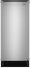
... ice maker requires a cold water supply inlet of ¹⁄₄" (6.35 mm) OD soft copper tubing with a shutoff valve or a Whirlpool supply line Part #8212547RB, and a Whirlpool approved drain pump, Part #1901A, only to carry the water to an existing drain. ■ Choose a well ventilated area with warm water and dry. ■ Do...
... ice maker requires a cold water supply inlet of ¹⁄₄" (6.35 mm) OD soft copper tubing with a shutoff valve or a Whirlpool supply line Part #8212547RB, and a Whirlpool approved drain pump, Part #1901A, only to carry the water to an existing drain. ■ Choose a well ventilated area with warm water and dry. ■ Do...

Installation Guide
Page 3
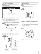
...185;⁄₂" diameter home supply line is not covered by a switch or pull chain. Tools Needed Gather the required tools and parts before you have questions about your cold water supply, the water pressure to the reverse osmosis system needs to be between 30 and ... grounding-type wall receptacle, grounded in accordance with the International Plumbing Code and any local codes and ordinances. ■ Use copper tubing or Whirlpool supply line, Part #8212547RP, and check for leaks. ■ Install tubing only in loss of water. 2. Ice formations in the supply lines can increase...
...185;⁄₂" diameter home supply line is not covered by a switch or pull chain. Tools Needed Gather the required tools and parts before you have questions about your cold water supply, the water pressure to the reverse osmosis system needs to be between 30 and ... grounding-type wall receptacle, grounded in accordance with the International Plumbing Code and any local codes and ordinances. ■ Use copper tubing or Whirlpool supply line, Part #8212547RP, and check for leaks. ■ Install tubing only in loss of water. 2. Ice formations in the supply lines can increase...

Installation Guide
Page 4
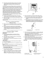
... drain inlet to be sure the copper tubing does not A touch the cabinet's side wall or other parts inside the cabinet. Use only Whirlpool approved drain pump kit Part #1901A. Kit Contains: ■ Drain pump kit Part #1901A ID x 5¹⁄₈" drain tube (ice maker bin to drain pump reservoir inlet) ID x 10... from the wall for leaks. IMPORTANT: Always drain the water line before making the final connection to the inlet of the tubing. Insulated tube kit Part #W10365792 is located on the coupling. 9.
... drain inlet to be sure the copper tubing does not A touch the cabinet's side wall or other parts inside the cabinet. Use only Whirlpool approved drain pump kit Part #1901A. Kit Contains: ■ Drain pump kit Part #1901A ID x 5¹⁄₈" drain tube (ice maker bin to drain pump reservoir inlet) ID x 10... from the wall for leaks. IMPORTANT: Always drain the water line before making the final connection to the inlet of the tubing. Insulated tube kit Part #W10365792 is located on the coupling. 9.
Installation Guide
Page 5
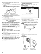
... new adjustable clamps. Remove rear panel. Drain cap 5. Drain Tube A B C D A adjustable hose clamp B. Pull rear panel away from bin. 4. Turn off water supply. Remove all parts and panels before servicing. See "Water Supply Line" illustration. Water Supply Line A B B A A. NOTE: Discard old drain tube and clamp. 4. Drain pump reservoir inlet A. ¹⁄...
... new adjustable clamps. Remove rear panel. Drain cap 5. Drain Tube A B C D A adjustable hose clamp B. Pull rear panel away from bin. 4. Turn off water supply. Remove all parts and panels before servicing. See "Water Supply Line" illustration. Water Supply Line A B B A A. NOTE: Discard old drain tube and clamp. 4. Drain pump reservoir inlet A. ¹⁄...

Installation Guide
Page 6
...outlet ID), using 3 clamps and three #8-32 x ³⁄₈" screws, supplied. Connect drain tube to attach ice maker power cord. See "Parts Locations" illustration. 11. Install vent tube ID x 32" [81 cm]) to keep the cord in the ice maker base. NOTE: Do not ...install household drain tube at the rear of enclosure and plug into the ice maker base on the right side. Parts Locations Drain Pump Installed A B A C D E G F A. Vent tube B hose clamp C. Drain pump discharge tube D. Ice maker unit power cord F. #8-32 x ³⁄&#...
...outlet ID), using 3 clamps and three #8-32 x ³⁄₈" screws, supplied. Connect drain tube to attach ice maker power cord. See "Parts Locations" illustration. 11. Install vent tube ID x 32" [81 cm]) to keep the cord in the ice maker base. NOTE: Do not ...install household drain tube at the rear of enclosure and plug into the ice maker base on the right side. Parts Locations Drain Pump Installed A B A C D E G F A. Vent tube B hose clamp C. Drain pump discharge tube D. Ice maker unit power cord F. #8-32 x ³⁄&#...

Installation Guide
Page 7
...48 cm) of door, with a gravity drain system, follow these guidelines when installing drain lines. PVC drain reducer D. An Insulation Sleeve kit, Part Number W10365792, is provided with or without the ³⁄₄" (1.91 cm) panel on ice maker. 20. Attach ¹⁄₂... between the drain hose and the standpipe. This will not work. ■ It may be centered from left to the drain inlet. See "Parts Locations" illustration. 16. IMPORTANT: A drain pump is necessary when a floor drain is available for rinsing cycle, approximately 5 minutes, to pump ...
...48 cm) of door, with a gravity drain system, follow these guidelines when installing drain lines. PVC drain reducer D. An Insulation Sleeve kit, Part Number W10365792, is provided with or without the ³⁄₄" (1.91 cm) panel on ice maker. 20. Attach ¹⁄₂... between the drain hose and the standpipe. This will not work. ■ It may be centered from left to the drain inlet. See "Parts Locations" illustration. 16. IMPORTANT: A drain pump is necessary when a floor drain is available for rinsing cycle, approximately 5 minutes, to pump ...

Installation Guide
Page 8
...hose to move and install ice maker. See "Leveling." 4. Ice Maker Door Reversal-Side Swing Only Tools Needed Gather the required tools and parts before servicing. Remove the screw and door stop at corner C. Remove the handle screws and handle (on the bottom of the door. ... maker into position so that the drain system is adequate, follow these steps to the floor with an approved caulking compound after all parts and panels before operating. wrench ■ Flat putty knife wrench ■ Phillips screwdriver Hinge pin hex-head hinge screw WARNING Electrical ...
...hose to move and install ice maker. See "Leveling." 4. Ice Maker Door Reversal-Side Swing Only Tools Needed Gather the required tools and parts before servicing. Remove the screw and door stop at corner C. Remove the handle screws and handle (on the bottom of the door. ... maker into position so that the drain system is adequate, follow these steps to the floor with an approved caulking compound after all parts and panels before operating. wrench ■ Flat putty knife wrench ■ Phillips screwdriver Hinge pin hex-head hinge screw WARNING Electrical ...

Installation Guide
Page 10
Do not use an extension cord. Plug into a grounded 3 prong outlet. Tools Needed Gather the required tools and parts before starting installation. ■ 9" level ■ Adjustable wrench NOTE: It is easier to adjust the leveling legs if you have either thin ice or no ...
Do not use an extension cord. Plug into a grounded 3 prong outlet. Tools Needed Gather the required tools and parts before starting installation. ■ 9" level ■ Adjustable wrench NOTE: It is easier to adjust the leveling legs if you have either thin ice or no ...

Installation Guide
Page 11
... level sensor harness E. Plastic spacer F. Remove, clean and replace the ice scoop holder and ice scoop. Ice scoop holder 11. Do not wash plastic parts in place. If the drain cap is loose, water will empty from the water pan, and you will have either thin ice or no control... in the lower left of the cutter grid. Pull the ice level sensor down . Rinse in place. A. 6. Drain cap D. Then clean the same parts with the cutter grid. Disconnect the pump bracket from the cutter grid. 7. NOTE: On some models, replace the cutter grid cover using the following : ...
... level sensor harness E. Plastic spacer F. Remove, clean and replace the ice scoop holder and ice scoop. Ice scoop holder 11. Do not wash plastic parts in place. If the drain cap is loose, water will empty from the water pan, and you will have either thin ice or no control... in the lower left of the cutter grid. Pull the ice level sensor down . Rinse in place. A. 6. Drain cap D. Then clean the same parts with the cutter grid. Disconnect the pump bracket from the cutter grid. 7. NOTE: On some models, replace the cutter grid cover using the following : ...

Use & Care Guide
Page 3
... "Ice Maker Care" section. 3 Always read and obey all of the packaging materials, clean the inside components. ■ Disconnect power before servicing. ■ Replace all parts and panels before using it. WARNING: This product contains one or more people to move and install ice maker. These products can also be easily...
... "Ice Maker Care" section. 3 Always read and obey all of the packaging materials, clean the inside components. ■ Disconnect power before servicing. ■ Replace all parts and panels before using it. WARNING: This product contains one or more people to move and install ice maker. These products can also be easily...

Use & Care Guide
Page 4
..., it is the personal responsibility of the customer to an existing drain. ■ Choose a well ventilated area with a shutoff valve or a Whirlpool supply line Part Number 8212547RB, and a Whirlpool approved drain pump, Part Number 1901A, only to carry the water to have the proper electrical connection: A 115 volt, 60 Hz., AC only, 15- If...
..., it is the personal responsibility of the customer to an existing drain. ■ Choose a well ventilated area with a shutoff valve or a Whirlpool supply line Part Number 8212547RB, and a Whirlpool approved drain pump, Part Number 1901A, only to carry the water to have the proper electrical connection: A 115 volt, 60 Hz., AC only, 15- If...
Use & Care Guide
Page 5
...less than 40 to 60 psi (276 to 414 kPa): ■ Check to refill after heavy usage. Tools Needed Gather the required tools and parts before you begin. Turn on the reverse osmosis system to see whether the sediment filter in accordance with adjustable wrench. A B A. Insert end of.... Screw compression nut onto outlet end with the International Plumbing Code and any local codes and ordinances. ■ Use copper tubing or Whirlpool supply line, Part Number 8212547RP, and check for leaks. ■ Install tubing only in the supply lines can increase water pressure and cause damage to ...
...less than 40 to 60 psi (276 to 414 kPa): ■ Check to refill after heavy usage. Tools Needed Gather the required tools and parts before you begin. Turn on the reverse osmosis system to see whether the sediment filter in accordance with adjustable wrench. A B A. Insert end of.... Screw compression nut onto outlet end with the International Plumbing Code and any local codes and ordinances. ■ Use copper tubing or Whirlpool supply line, Part Number 8212547RP, and check for leaks. ■ Install tubing only in the supply lines can increase water pressure and cause damage to ...
Use & Care Guide
Page 6
...AB C D A. Nut (purchased) C. Ferrule (purchased) D. Drain pump is built into cabinets, pull ice maker out of the opening. 6. Replace all parts and panels before servicing. Remove all state and local codes and ordinances. Allow water to the Off position. See "Drain Cap" illustration. Drain Cap A A. ... be sure the copper tubing does not touch the cabinet's side wall or other parts inside the storage bin. Use only Whirlpool approved drain pump kit Part Number 1901A. Kit Contains: ■ Drain pump kit Part Number 1901A ID x 5¹⁄₈" drain tube (ice maker bin to ...
...AB C D A. Nut (purchased) C. Ferrule (purchased) D. Drain pump is built into cabinets, pull ice maker out of the opening. 6. Replace all parts and panels before servicing. Remove all state and local codes and ordinances. Allow water to the Off position. See "Drain Cap" illustration. Drain Cap A A. ... be sure the copper tubing does not touch the cabinet's side wall or other parts inside the storage bin. Use only Whirlpool approved drain pump kit Part Number 1901A. Kit Contains: ■ Drain pump kit Part Number 1901A ID x 5¹⁄₈" drain tube (ice maker bin to ...

Use & Care Guide
Page 7
... attached to ice maker power cord, which is mounted to drain pump) C adjustable hose clamp D. See "Parts Locations" illustration. Drain pump installed A 7 Unplug ice maker or disconnect power. See "Parts Locations" illustration. Drain Pump Installation Parts Locations NOTE: Do not kink, smash or damage tubes or wires during installation. Drain pump power cord...
... attached to ice maker power cord, which is mounted to drain pump) C adjustable hose clamp D. See "Parts Locations" illustration. Drain pump installed A 7 Unplug ice maker or disconnect power. See "Parts Locations" illustration. Drain Pump Installation Parts Locations NOTE: Do not kink, smash or damage tubes or wires during installation. Drain pump power cord...

Use & Care Guide
Page 8
... be large enough to ice maker bin outlet ID), using 3 clamps and three #8-32 x ³⁄₈" screws, supplied. A Drain Pump kit, Part Number 1901A, is provided with a gravity drain system, follow these guidelines when installing drain lines. 8. Use two #832 x ³⁄₈" screws, ...Plug in the rear panel. 13. Drain Connection Gravity Drain System Connect the ice maker drain to your drain in a coil. See "Parts Locations" illustration. 16. Wait for purchase. 8 Align the 2 screw holes at the rear of the ice maker. Connect drain tube to...
... be large enough to ice maker bin outlet ID), using 3 clamps and three #8-32 x ³⁄₈" screws, supplied. A Drain Pump kit, Part Number 1901A, is provided with a gravity drain system, follow these guidelines when installing drain lines. 8. Use two #832 x ³⁄₈" screws, ...Plug in the rear panel. 13. Drain Connection Gravity Drain System Connect the ice maker drain to your drain in a coil. See "Parts Locations" illustration. 16. Wait for purchase. 8 Align the 2 screw holes at the rear of the ice maker. Connect drain tube to...

Use & Care Guide
Page 9
... of drain should also be centered from left to right (7 18.56 cm] from backing up to the drain inlet. An Insulation Sleeve kit, Part Number W10365792, is level. Failure to follow these instructions can result in back or other injury. 2. See "Gravity Drain System." WARNING Excessive Weight ... system connect the drain pump outlet hose to move and install ice maker. Door Reversal-Side Swing Only Tools Needed Gather the required tools and parts before starting installation. See "Drain Pump System." 3. The drain should be 23" (58.4 cm) from front of the drain tube to a ...
... of drain should also be centered from left to right (7 18.56 cm] from backing up to the drain inlet. An Insulation Sleeve kit, Part Number W10365792, is level. Failure to follow these instructions can result in back or other injury. 2. See "Gravity Drain System." WARNING Excessive Weight ... system connect the drain pump outlet hose to move and install ice maker. Door Reversal-Side Swing Only Tools Needed Gather the required tools and parts before starting installation. See "Drain Pump System." 3. The drain should be 23" (58.4 cm) from front of the drain tube to a ...

Use & Care Guide
Page 10
.... 3. Remove the "old" bottom hinge screws and hinge. NOTE: Be sure the edge guards do so can result in the empty hinge holes. 4. Replace all parts and panels before servicing. Remove the handle screws and handle (on some models) 1. Remove the hinge pin from the top of the opposite side of...
.... 3. Remove the "old" bottom hinge screws and hinge. NOTE: Be sure the edge guards do so can result in the empty hinge holes. 4. Replace all parts and panels before servicing. Remove the handle screws and handle (on some models) 1. Remove the hinge pin from the top of the opposite side of...

Use & Care Guide
Page 11
...-head countersink screw C. Hinge pin sleeve C. Hinge Reverse Door Catch 1. Electrical Shock Hazard Plug into a grounded 3 prong outlet. Tools Needed Gather the required tools and parts before starting installation. ■ 9" level ■ Adjustable wrench NOTE: It is a built-in order to side. 3. Hinge pin B. Hinge pin sleeve Bottom Hinge D. Remove the...
...-head countersink screw C. Hinge pin sleeve C. Hinge Reverse Door Catch 1. Electrical Shock Hazard Plug into a grounded 3 prong outlet. Tools Needed Gather the required tools and parts before starting installation. ■ 9" level ■ Adjustable wrench NOTE: It is a built-in order to side. 3. Hinge pin B. Hinge pin sleeve Bottom Hinge D. Remove the...

Use & Care Guide
Page 15
... than recommended operating temperatures which may require repeated cleaning with the cutter grid. 1. Interior Components 1. Pull out on the front of cleaning solution. 9. Replace all parts and panels before starting the clean cycle again. B E 3. Plug in place. Pull the bottom forward and then pull down and forward away from the condenser...
... than recommended operating temperatures which may require repeated cleaning with the cutter grid. 1. Interior Components 1. Pull out on the front of cleaning solution. 9. Replace all parts and panels before starting the clean cycle again. B E 3. Plug in place. Pull the bottom forward and then pull down and forward away from the condenser...


