
Uk Manual
Page 5
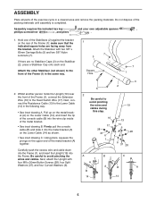
.... ASSEMBLY Place all parts of the metal bracket (A) together. Carefully push the excess wire and cable down into the Frame (1), and insert the Upright (19) into the wire clip inside of the Frame (1), connect the Extension Wire (16) to the Lower Cable (14) in the same way. Attach the Stabiliser with ...A A B 14 B C A B A 14 5 Next, connect the Resistance Cable (13) to the Reed Switch Wire (17). Be careful to the front of the console cable (B) into the Frame. Hold one of the Stabilisers (2) against the bracket on the Lower Cable (14), and insert the tip of the...
.... ASSEMBLY Place all parts of the metal bracket (A) together. Carefully push the excess wire and cable down into the Frame (1), and insert the Upright (19) into the wire clip inside of the Frame (1), connect the Extension Wire (16) to the Lower Cable (14) in the same way. Attach the Stabiliser with ...A A B 14 B C A B A 14 5 Next, connect the Resistance Cable (13) to the Reed Switch Wire (17). Be careful to the front of the console cable (B) into the Frame. Hold one of the Stabilisers (2) against the bracket on the Lower Cable (14), and insert the tip of the...
Uk Manual
Page 6
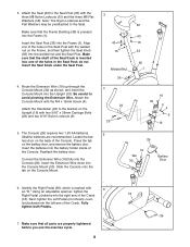
... use the exercise cycle. 6 Note: The Nylon Locknuts and the Flat Washers may be preattached to avoid pinching the Extension Wire. Make sure that the Frame Bushing (35) is marked with the three M8 Nylon Locknuts (15) and the three M8 Flat Washers (43). Attach the Console Mount with two 5/16... batteries. Slide the Console onto the tab on the battery door, and remove the battery door. Attach the Seat (32) to the bracket on the Frame, and then tighten the Seat Knob (36) into the welded nut and the Seat Post. Identify the Right Pedal (39), which is pressed into the...
... use the exercise cycle. 6 Note: The Nylon Locknuts and the Flat Washers may be preattached to avoid pinching the Extension Wire. Make sure that the Frame Bushing (35) is marked with the three M8 Nylon Locknuts (15) and the three M8 Flat Washers (43). Attach the Console Mount with two 5/16... batteries. Slide the Console onto the tab on the battery door, and remove the battery door. Attach the Seat (32) to the bracket on the Frame, and then tighten the Seat Knob (36) into the welded nut and the Seat Post. Identify the Right Pedal (39), which is pressed into the...
Uk Manual
Page 7
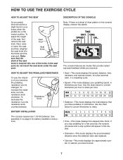
Resistance Knob BATTERY INSTALLATION The console requires two 1.5V AA batteries. DESCRIPTION OF THE CONSOLE Note: If there is inserted into Seat Knob the frame and the seat post. Use the chart below to convert kilometres to miles per hour to miles. • Time-This mode displays the elapsed time. ...
Resistance Knob BATTERY INSTALLATION The console requires two 1.5V AA batteries. DESCRIPTION OF THE CONSOLE Note: If there is inserted into Seat Knob the frame and the seat post. Use the chart below to convert kilometres to miles per hour to miles. • Time-This mode displays the elapsed time. ...
Uk Manual
Page 10
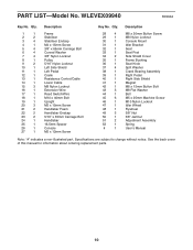
... # 1 Description M8 x 20mm Button Screw M8 Nylon Locknut Console Mount Idler Bracket Seat Seat Post Side Shield Cover Frame Bushing Seat Knob Split Washer Crank Bearing Assembly Right Pedal Right Side Shield Magnet M8 x 15mm Button Bolt M8 Flat Washer...4 6 4 7 4 8 1 9 2 10 1 11 1 12 1 13 1 14 1 15 3 16 1 17 1 18 1 19 1 20 3 21 2 22 2 23 2 24 1 25 1 26 1 27 1 Description Frame Stabiliser Stabiliser Endcap M4 x 15mm Screw 3/8" x 65mm Carriage Bolt Curved Washer 3/8" Nylon Locknut Pulley 5/16" Nylon Locknut Left Side Shield Left Pedal Crank Resistance...
... # 1 Description M8 x 20mm Button Screw M8 Nylon Locknut Console Mount Idler Bracket Seat Seat Post Side Shield Cover Frame Bushing Seat Knob Split Washer Crank Bearing Assembly Right Pedal Right Side Shield Magnet M8 x 15mm Button Bolt M8 Flat Washer...4 6 4 7 4 8 1 9 2 10 1 11 1 12 1 13 1 14 1 15 3 16 1 17 1 18 1 19 1 20 3 21 2 22 2 23 2 24 1 25 1 26 1 27 1 Description Frame Stabiliser Stabiliser Endcap M4 x 15mm Screw 3/8" x 65mm Carriage Bolt Curved Washer 3/8" Nylon Locknut Pulley 5/16" Nylon Locknut Left Side Shield Left Pedal Crank Resistance...