
English Manual
Page 1
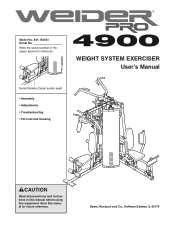
WEIGHT SYSTEM EXERCISER User's Manual Serial Number Decal (under seat) • Assembly • Adjustments • Troubleshooting • Part List and Drawing CAUTION Read all precautions and instructions in the space above for future reference. Save this equipment. Model No. 831.154031 Serial No. Sears, Roebuck and Co., Hoffman Estates, IL 60179 Write the serial number in this manual before using this manual for reference.
WEIGHT SYSTEM EXERCISER User's Manual Serial Number Decal (under seat) • Assembly • Adjustments • Troubleshooting • Part List and Drawing CAUTION Read all precautions and instructions in the space above for future reference. Save this equipment. Model No. 831.154031 Serial No. Sears, Roebuck and Co., Hoffman Estates, IL 60179 Write the serial number in this manual before using this manual for reference.
English Manual
Page 2
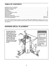
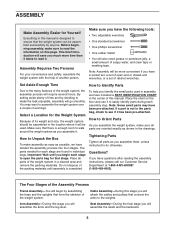
If the decal is missing or illegible, please call toll-free 1-877-992-5999, Monday through Friday, 6 a.m. until 6 p.m. Apply the decal in the center of this manual. TABLE OF CONTENTS WARNING DECAL PLACEMENT 2 IMPORTANT PRECAUTIONS 3 BEFORE YOU BEGIN 4 ASSEMBLY 5 ADJUSTMENTS 24 WEIGHT RESISTANCE CHART 26 CABLE DIAGRAM 27 MAINTENANCE 29 EXERCISE GUIDELINES 30 ORDERING REPLACEMENT PARTS Back Cover FULL 90-DAY WARRANTY Back Cover Note: A PART IDENTIFICATION CHART and a PART LIST/EXPLODED DRAWING are attached in the location shown. 2 Mountain Time, to order a free replacement decal....
If the decal is missing or illegible, please call toll-free 1-877-992-5999, Monday through Friday, 6 a.m. until 6 p.m. Apply the decal in the center of this manual. TABLE OF CONTENTS WARNING DECAL PLACEMENT 2 IMPORTANT PRECAUTIONS 3 BEFORE YOU BEGIN 4 ASSEMBLY 5 ADJUSTMENTS 24 WEIGHT RESISTANCE CHART 26 CABLE DIAGRAM 27 MAINTENANCE 29 EXERCISE GUIDELINES 30 ORDERING REPLACEMENT PARTS Back Cover FULL 90-DAY WARRANTY Back Cover Note: A PART IDENTIFICATION CHART and a PART LIST/EXPLODED DRAWING are attached in the location shown. 2 Mountain Time, to order a free replacement decal....
English Manual
Page 3
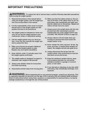
The weight system is intended for persons over the age of serious injury, read the following important precautions before using the weight system. 1. Do not use the weight system in this manual before using the weight system. Never release the arms, leg lever, lat bar, leg press, ab strap, or handle while weights are properly tightened each time the weight system is especially important for home use the lat bar. 7. Do not put the resistance system in this manual. 2. This is used. Cover the floor beneath the weight system to ensure that all users of the weight ...
The weight system is intended for persons over the age of serious injury, read the following important precautions before using the weight system. 1. Do not use the weight system in this manual before using the weight system. Never release the arms, leg lever, lat bar, leg press, ab strap, or handle while weights are properly tightened each time the weight system is especially important for home use the lat bar. 7. Do not put the resistance system in this manual. 2. This is used. Cover the floor beneath the weight system to ensure that all users of the weight ...
English Manual
Page 4
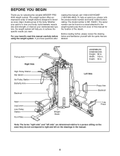
... and familiarize yourself with the parts that are determined relative to the weight system (see the front cover of this manual for selecting the versatile WEIDER® PRO 4900 weight system. The model number is to right and left side" are labeled. Depth: 94 in the manual. 4 Whether your cardiovascular system, the weight...
... and familiarize yourself with the parts that are determined relative to the weight system (see the front cover of this manual for selecting the versatile WEIDER® PRO 4900 weight system. The model number is to right and left side" are labeled. Depth: 94 in the manual. 4 Whether your cardiovascular system, the weight...
English Manual
Page 5
This brief introduction will save you much more convenient if you have a socket set, a set of ratchet wrenches. You may have been pre-attached. Make sure that there is enough room to walk around the weight system as possible, we have included a PART IDENTIFICATION CHART in the center of this manual. Important: Wait until assembly is completed. Make sure you assemble it has been pre-attached. How to Unpack the Box To make sure to read it. Note: Some small parts may want to assemble the weight system over a couple of evenings. If a part is not in the parts bag, ...
This brief introduction will save you much more convenient if you have a socket set, a set of ratchet wrenches. You may have been pre-attached. Make sure that there is enough room to walk around the weight system as possible, we have included a PART IDENTIFICATION CHART in the center of this manual. Important: Wait until assembly is completed. Make sure you assemble it has been pre-attached. How to Unpack the Box To make sure to read it. Note: Some small parts may want to assemble the weight system over a couple of evenings. If a part is not in the parts bag, ...
English Manual
Page 6
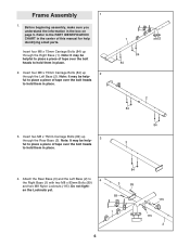
Note: It may be help- Insert two M8 x 75mm Carriage Bolts (84) up 3 through the Left Base (2). Do not tight- Refer to the PART IDENTIFICATION CHART in the center of tape over the bolt heads to hold them in place. 3. Insert four M8 x 75mm Carriage Bolts (84) up through the Right Base (1). ful to hold them in the box on page 5. Note: It may be helpful to place a piece of tape over the bolt heads to place a piece of this manual for help - Before beginning assembly, make sure you understand the information in place. 1 84 84 2 84 84 3 4. Frame Assembly 1 1. ...
Note: It may be help- Insert two M8 x 75mm Carriage Bolts (84) up 3 through the Left Base (2). Do not tight- Refer to the PART IDENTIFICATION CHART in the center of tape over the bolt heads to hold them in place. 3. Insert four M8 x 75mm Carriage Bolts (84) up through the Right Base (1). ful to hold them in the box on page 5. Note: It may be helpful to place a piece of tape over the bolt heads to place a piece of this manual for help - Before beginning assembly, make sure you understand the information in place. 1 84 84 2 84 84 3 4. Frame Assembly 1 1. ...
English Manual
Page 7
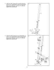
Do not tighten the Locknuts yet. 3 115 115 84 4 115 115 1 84 7 Attach the Rear Upright (6) to the Right Base (1) 6 with the two indicated M8 x 75mm Carriage Bolts (84) and two M8 Nylon Locknuts (115). Do not tighten the Locknuts yet. 6 6. Attach the Right Upright (4) to the Rear Base (3) 5 with the two indicated M8 x 75mm Carriage Bolts (84) and two M8 Nylon Locknuts (115). 5.
Do not tighten the Locknuts yet. 3 115 115 84 4 115 115 1 84 7 Attach the Rear Upright (6) to the Right Base (1) 6 with the two indicated M8 x 75mm Carriage Bolts (84) and two M8 Nylon Locknuts (115). Do not tighten the Locknuts yet. 6 6. Attach the Right Upright (4) to the Rear Base (3) 5 with the two indicated M8 x 75mm Carriage Bolts (84) and two M8 Nylon Locknuts (115). 5.
English Manual
Page 8
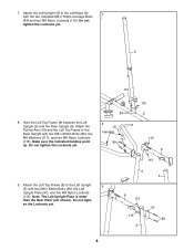
Note: The Left Upright Plate is wider than the Rear Plate (not shown). Attach the Left Top Frame (8) to the Left Upright 9 (5) with the two indicated M8 x 75mm Carriage Bolts (84) and two M8 Nylon Locknuts (115). Do not tight- Do not tighten the Locknuts yet. 84 8 19 Handles 117 89 115 2 115 8 115 9. 7. Attach the Left Upright (5) to the Rear Upright with two M8 x 83mm Bolts (89), two M8 Washers (117), and two M8 Nylon Locknuts (115). Do not tighten the Locknuts yet. 5 115 8. Hold the Left Top Frame (8) between the Left Upright (5) and the Rear Upright (6). en the ...
Note: The Left Upright Plate is wider than the Rear Plate (not shown). Attach the Left Top Frame (8) to the Left Upright 9 (5) with the two indicated M8 x 75mm Carriage Bolts (84) and two M8 Nylon Locknuts (115). Do not tight- Do not tighten the Locknuts yet. 84 8 19 Handles 117 89 115 2 115 8 115 9. 7. Attach the Left Upright (5) to the Rear Upright with two M8 x 83mm Bolts (89), two M8 Washers (117), and two M8 Nylon Locknuts (115). Do not tighten the Locknuts yet. 5 115 8. Hold the Left Top Frame (8) between the Left Upright (5) and the Rear Upright (6). en the ...
English Manual
Page 9
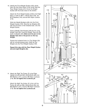
Orient the Weight Guides with the holes closer to the bottom. 10 136 Attach the Front Weight Guides (136) to the Right Upright (4) with the pin holes on the top Weight. Slide the ten Weights (35), with two M8 x 80mm Bolts (94), two M8 Washers (117), and two M8 Nylon Locknuts (115). Attach the Right Top Frame (7) to the Right 24 Base (1) with two M8 x 80mm Bolts (94), two M8 Washers (117), and two M8 Nylon Locknuts (115). Insert the Weight Tube into the Long Weight Tube (36). Do not tighten the Locknuts yet. 24 35 65 130 116 116 114 1 11 94 117 7 115 4 115...
Orient the Weight Guides with the holes closer to the bottom. 10 136 Attach the Front Weight Guides (136) to the Right Upright (4) with the pin holes on the top Weight. Slide the ten Weights (35), with two M8 x 80mm Bolts (94), two M8 Washers (117), and two M8 Nylon Locknuts (115). Attach the Right Top Frame (7) to the Right 24 Base (1) with two M8 x 80mm Bolts (94), two M8 Washers (117), and two M8 Nylon Locknuts (115). Insert the Weight Tube into the Long Weight Tube (36). Do not tighten the Locknuts yet. 24 35 65 130 116 116 114 1 11 94 117 7 115 4 115...
English Manual
Page 10
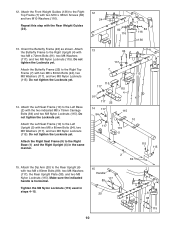
Attach the Front Weight Guides (136) to the Right Top Frame (7) with two M8 x 72mm Bolts (91), two M8 Washers (117), and two M8 Nylon Locknuts (115). Attach the Butterfly Frame to the Left Base (2) with two M8 x 80mm Bolts (94), two M8 Washers (117), and two M8 Nylon Locknuts (115). Do not tighten the Locknuts yet. 14. Attach the Left Seat Frame (10) to the Right Upright (4) with two M10 x 38mm Screws (82) and two M10 Washers (116). Orient the Butterfly Frame (22) as shown. Attach the Butterfly Frame (22) to the Right Base (1) and the Right Upright (4) in steps 4-15. 13 94 117 ...
Attach the Front Weight Guides (136) to the Right Top Frame (7) with two M8 x 72mm Bolts (91), two M8 Washers (117), and two M8 Nylon Locknuts (115). Attach the Butterfly Frame to the Left Base (2) with two M8 x 80mm Bolts (94), two M8 Washers (117), and two M8 Nylon Locknuts (115). Do not tighten the Locknuts yet. 14. Attach the Left Seat Frame (10) to the Right Upright (4) with two M10 x 38mm Screws (82) and two M10 Washers (116). Orient the Butterfly Frame (22) as shown. Attach the Butterfly Frame (22) to the Right Base (1) and the Right Upright (4) in steps 4-15. 13 94 117 ...
English Manual
Page 11
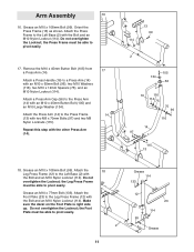
the Leg Press Frame must be able to pivot easily. 17. Grease an M10 x 108mm Bolt (99). Orient the Press Frame (13) as shown. Attach a Press Handle (16) to the Press Arm (14) with an M10 x 45mm Button Bolt (105) and an M10 Large Washer (134). Attach a Press Arm Cap (56) to a Press Arm (14) with two M8 x 70mm Bolts (97) and two M8 Nylon Locknuts (115). Grease an M10 x 108mm Bolt (99). Do not overtighten the Locknut; Attach the Foot Plate (23) to the Press Frame (13) with an M10 x 65mm Bolt (96), two M10 Washers (116), two M10 x 12mm Spacers (75), and an M10 Nylon Locknut (...
the Leg Press Frame must be able to pivot easily. 17. Grease an M10 x 108mm Bolt (99). Orient the Press Frame (13) as shown. Attach a Press Handle (16) to the Press Arm (14) with an M10 x 45mm Button Bolt (105) and an M10 Large Washer (134). Attach a Press Arm Cap (56) to a Press Arm (14) with two M8 x 70mm Bolts (97) and two M8 Nylon Locknuts (115). Grease an M10 x 108mm Bolt (99). Do not overtighten the Locknut; Attach the Foot Plate (23) to the Press Frame (13) with an M10 x 65mm Bolt (96), two M10 Washers (116), two M10 x 12mm Spacers (75), and an M10 Nylon Locknut (...
English Manual
Page 12
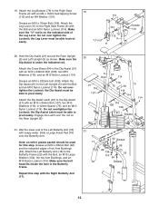
19. Attach the Cross Brace (64) to the Dip Assist (21) with an M10 x 85mm Bolt (107), two M10 Washers (116), a 12mm Spacer (75), and an M10 Nylon Locknut (114). Attach the Dip Assist Latch (67) to the Butterfly Frame (22) with an M4 x 16mm Self-tapping Screw (113) and an M4 Washer (131). 114 Grease an M10 x 75mm Bolt (104). Attach the Left Butterfly Arm (18) to the Dip Assist (21) with an M10 x 232mm Bolt (108), two M10 Washers (116), and an M10 Nylon Locknut (114). Repeat this step. the Leg Lever must be able to pivot easily. 131 "U"-rod 76 113 9 11 Grease 104 20....
19. Attach the Cross Brace (64) to the Dip Assist (21) with an M10 x 85mm Bolt (107), two M10 Washers (116), a 12mm Spacer (75), and an M10 Nylon Locknut (114). Attach the Dip Assist Latch (67) to the Butterfly Frame (22) with an M4 x 16mm Self-tapping Screw (113) and an M4 Washer (131). 114 Grease an M10 x 75mm Bolt (104). Attach the Left Butterfly Arm (18) to the Dip Assist (21) with an M10 x 232mm Bolt (108), two M10 Washers (116), and an M10 Nylon Locknut (114). Repeat this step. the Leg Lever must be able to pivot easily. 131 "U"-rod 76 113 9 11 Grease 104 20....
English Manual
Page 13
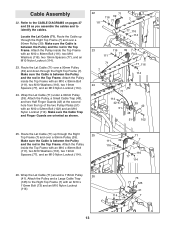
Cable Assembly 22. Attach the Pulley inside the Top Frame with an M10 x 110mm Bolt (73) and an M10 Nylon Locknut (114). 73 71 125 41 114 7 13 Make sure the Cable Trap and Finger Guards are oriented as you assemble the cables and to identify the cables. Attach the Pulley and a Large Cable Trap (125) to the CABLE DIAGRAMS on pages 27 and 28 as shown. 22 71 116 39 77 7 111 77 116 114 23 116 39 111 77 Rod 71 7 77 116 114 24 71 114 42 51 39 42 48 51 102 25. Refer to the Right Top Frame (7) with an M10 x 80mm Bolt (111), two M10 Washers (116), two 19mm Spacers...
Cable Assembly 22. Attach the Pulley inside the Top Frame with an M10 x 110mm Bolt (73) and an M10 Nylon Locknut (114). 73 71 125 41 114 7 13 Make sure the Cable Trap and Finger Guards are oriented as you assemble the cables and to identify the cables. Attach the Pulley and a Large Cable Trap (125) to the CABLE DIAGRAMS on pages 27 and 28 as shown. 22 71 116 39 77 7 111 77 116 114 23 116 39 111 77 Rod 71 7 77 116 114 24 71 114 42 51 39 42 48 51 102 25. Refer to the Right Top Frame (7) with an M10 x 80mm Bolt (111), two M10 Washers (116), two 19mm Spacers...
English Manual
Page 14
Wrap the Lat Cable (71) under a 90mm Pulley 31 (39). Make sure that the rod is oriented as shown. Make sure the Cable Trap is inserted through the Left Top Frame (8). Locate the Ab Cable (72). Route the Lat Cable (71) over a 90mm Pulley 27 (39) and down through both Quarter Guards and is against the bracket. 28 21 116 108 29 71 74 74 116 43 39 48 43 114 116 88 71 115 6 30. Attach the Pulley inside the Top Frame with an M10 x 108mm Bolt (99), an M10 Washer (116), and an M10 Nylon Locknut (114). Attach the Pulley and the two Quarter Guards (95) to ...
Wrap the Lat Cable (71) under a 90mm Pulley 31 (39). Make sure that the rod is oriented as shown. Make sure the Cable Trap is inserted through the Left Top Frame (8). Locate the Ab Cable (72). Route the Lat Cable (71) over a 90mm Pulley 27 (39) and down through both Quarter Guards and is against the bracket. 28 21 116 108 29 71 74 74 116 43 39 48 43 114 116 88 71 115 6 30. Attach the Pulley inside the Top Frame with an M10 x 108mm Bolt (99), an M10 Washer (116), and an M10 Nylon Locknut (114). Attach the Pulley and the two Quarter Guards (95) to ...
English Manual
Page 15
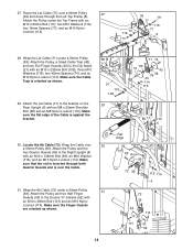
Make sure the Cable Trap is oriented to the Left Butterfly Arm (18) with an M10 x 61mm Bolt (90) and an M10 Nylon Locknut (114). Wrap the Ab Cable (72) around a "V"-pulley (40). 33 Attach the "V"-pulley, a Cable Trap (49), an M10 Washer (116), and two Full Finger Guards (43) to hold the Cable in the groove of the Pulley. 34. 32. Wrap the Ab Cable (72) around a "V"-pulley (40). 34 Attach the "V"-pulley, a Cable Trap (49), an M10 Washer (116), and two Full Finger Guards (43) to hold the Cable in the groove of the Pulley. 4 43 49 40 116 43 72 90 114 33. Wrap...
Make sure the Cable Trap is oriented to the Left Butterfly Arm (18) with an M10 x 61mm Bolt (90) and an M10 Nylon Locknut (114). Wrap the Ab Cable (72) around a "V"-pulley (40). 33 Attach the "V"-pulley, a Cable Trap (49), an M10 Washer (116), and two Full Finger Guards (43) to hold the Cable in the groove of the Pulley. 34. 32. Wrap the Ab Cable (72) around a "V"-pulley (40). 34 Attach the "V"-pulley, a Cable Trap (49), an M10 Washer (116), and two Full Finger Guards (43) to hold the Cable in the groove of the Pulley. 4 43 49 40 116 43 72 90 114 33. Wrap...
English Manual
Page 16
Make sure the flat edge of the Cable is over the rod in the Seat Frame. 116 75 Attach a 90mm Pulley (39) inside the Right Seat 38 Frame (9), over a 90mm 40 Pulley (39). Route the 37 Cable through the Right 39 Upright (4) and under a 90mm Pulley (39). Attach a 90mm Pulley (39) inside the Leg Lever (11), over the Leg Lever Cable (70), with an M10 x 65mm Bolt (96), two M10 Washers (116), two 12mm Spacers (75), and an M10 Nylon Locknut (114). 114 11 70 39 9 Rod 116 75 96 38. 36. Locate the Leg Lever Cable (70). Route the Leg Lever Cable (70) through the Leg Lever (11) and ...
Make sure the flat edge of the Cable is over the rod in the Seat Frame. 116 75 Attach a 90mm Pulley (39) inside the Right Seat 38 Frame (9), over a 90mm 40 Pulley (39). Route the 37 Cable through the Right 39 Upright (4) and under a 90mm Pulley (39). Attach a 90mm Pulley (39) inside the Leg Lever (11), over the Leg Lever Cable (70), with an M10 x 65mm Bolt (96), two M10 Washers (116), two 12mm Spacers (75), and an M10 Nylon Locknut (114). 114 11 70 39 9 Rod 116 75 96 38. 36. Locate the Leg Lever Cable (70). Route the Leg Lever Cable (70) through the Leg Lever (11) and ...
English Manual
Page 17
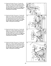
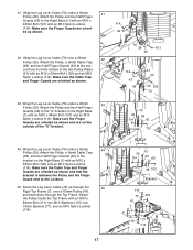
41. Attach the Pulley and two Half Finger Guards (42) to the Locknut. 45. Attach the Pulley, a Small Cable Trap (48), and two Half Finger Guards (42) at the sec- Make sure the Cable Trap and Finger Guards are oriented as shown. 43. Wrap the Leg Lever Cable (70) under a 90mm 41 Pulley (39). Make sure the Cable Trap and Finger Guards are oriented as shown and that the bracket is between the Pulley and the Finger Guard next to the Right Base (1) with an M10 x 80mm Bolt (111), two M10 Washers (116), two 19mm Spacers (77), and an M10 Nylon Locknut (114). 1 70 42 ...
41. Attach the Pulley and two Half Finger Guards (42) to the Locknut. 45. Attach the Pulley, a Small Cable Trap (48), and two Half Finger Guards (42) at the sec- Make sure the Cable Trap and Finger Guards are oriented as shown. 43. Wrap the Leg Lever Cable (70) under a 90mm 41 Pulley (39). Make sure the Cable Trap and Finger Guards are oriented as shown and that the bracket is between the Pulley and the Finger Guard next to the Right Base (1) with an M10 x 80mm Bolt (111), two M10 Washers (116), two 19mm Spacers (77), and an M10 Nylon Locknut (114). 1 70 42 ...
English Manual
Page 18
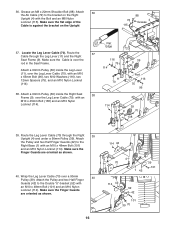
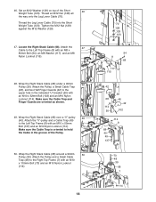
Thread the Leg Lever Cable (70) into the Short Weight Tube (123). Locate the Right Stack Cable (68). Make sure the Cable Trap and Finger Guards are oriented as shown. 49. Make sure the Cable Trap is oriented to hold the Cable in the indicated "U"-bracket (50) with an M10 x 110mm Bolt (73) and an M10 Nylon Locknut (114). 18 70 128 129 123 94 8 68 117 115 42 39 68 48 42 114 50 102 114 8 68 40 49 137 73 48 39 68 7 114 Wrap the Right Stack Cable (68) under a 90mm 48 Pulley (39). Tighten the M12 Nut (128) against the M12 Washer (129). 47. Attach the 47 ...
Thread the Leg Lever Cable (70) into the Short Weight Tube (123). Locate the Right Stack Cable (68). Make sure the Cable Trap and Finger Guards are oriented as shown. 49. Make sure the Cable Trap is oriented to hold the Cable in the indicated "U"-bracket (50) with an M10 x 110mm Bolt (73) and an M10 Nylon Locknut (114). 18 70 128 129 123 94 8 68 117 115 42 39 68 48 42 114 50 102 114 8 68 40 49 137 73 48 39 68 7 114 Wrap the Right Stack Cable (68) under a 90mm 48 Pulley (39). Tighten the M12 Nut (128) against the M12 Washer (129). 47. Attach the 47 ...
English Manual
Page 19
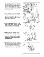
Set an M12 Washer (129) on the same side of the Long 52 Weight Tube (36). Make sure the Cable Trap and Finger Guards are oriented as shown. 55. Make sure the Finger Guards are oriented as shown. 53 117 69 86 115 12 54 114 116 10 42 48 42 69 106 39 116 55 116 114 12 69 40 42 100 116 116 42 19 Thread an M12 Nut (128) all the way onto the Right Stack Cable (68). Attach the Pulley, two Half Finger Guards (42), a Small Cable Trap (48), and an M10 Washer (116) to the Leg Press Frame (12) with an M10 x 103mm Bolt (106), an M10 Washer (116), and an M10 Nylon Locknut (...
Set an M12 Washer (129) on the same side of the Long 52 Weight Tube (36). Make sure the Cable Trap and Finger Guards are oriented as shown. 55. Make sure the Finger Guards are oriented as shown. 53 117 69 86 115 12 54 114 116 10 42 48 42 69 106 39 116 55 116 114 12 69 40 42 100 116 116 42 19 Thread an M12 Nut (128) all the way onto the Right Stack Cable (68). Attach the Pulley, two Half Finger Guards (42), a Small Cable Trap (48), and an M10 Washer (116) to the Leg Press Frame (12) with an M10 x 103mm Bolt (106), an M10 Washer (116), and an M10 Nylon Locknut (...
English Manual
Page 20
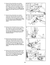
Wrap the Press Cable (69) around a "V"-pulley 58 (40). Attach the Pulley, two Half Finger Guards (42), a Small Cable Trap (48), and an M10 Washer (116) to the Left Upright (5) with an M10 x 135mm Bolt (98). Attach the Pulley, two Half Finger Guards (42), a Small Cable Trap (48), and an M10 Washer (116) to the Press Frame (13) with an M10 x 68mm Bolt (93) and an M10 Nylon Locknut (114). Make sure the Cable Trap and Finger Guards are oriented as shown. 20 42 114 39 48 116 42 98 13 116 42 69 42 116 39 102 114 2 Attach the Pulley, two Half Finger Guards (42), a Small ...
Wrap the Press Cable (69) around a "V"-pulley 58 (40). Attach the Pulley, two Half Finger Guards (42), a Small Cable Trap (48), and an M10 Washer (116) to the Left Upright (5) with an M10 x 135mm Bolt (98). Attach the Pulley, two Half Finger Guards (42), a Small Cable Trap (48), and an M10 Washer (116) to the Press Frame (13) with an M10 x 68mm Bolt (93) and an M10 Nylon Locknut (114). Make sure the Cable Trap and Finger Guards are oriented as shown. 20 42 114 39 48 116 42 98 13 116 42 69 42 116 39 102 114 2 Attach the Pulley, two Half Finger Guards (42), a Small ...