

User Manual
Page 1
Save this equipment. USER'S MANUAL Visit our website at www.weiderfitness.com new products, prizes, fitness tips, and much more! Write the serial number in this manual before using this manual for future reference. As a manufacturer, we are missing or damaged parts, we will provide immediate assistance, free of charge to providing complete customer satisfaction. TO AVOID UNNECESSARY DELAYS, PLEASE CALL DIRECT TO OUR TOLL-FREE CUSTOMER HOT LINE. The trained technicians on our customer hot line will guarantee complete satisfaction through direct assistance from our factory. ...
Save this equipment. USER'S MANUAL Visit our website at www.weiderfitness.com new products, prizes, fitness tips, and much more! Write the serial number in this manual before using this manual for future reference. As a manufacturer, we are missing or damaged parts, we will provide immediate assistance, free of charge to providing complete customer satisfaction. TO AVOID UNNECESSARY DELAYS, PLEASE CALL DIRECT TO OUR TOLL-FREE CUSTOMER HOT LINE. The trained technicians on our customer hot line will guarantee complete satisfaction through direct assistance from our factory. ...
User Manual
Page 2
TABLE OF CONTENTS IMPORTANT PRECAUTIONS 3 BEFORE YOU BEGIN 4 ASSEMBLY 5 ADJUSTMENTS 22 WEIGHT RESISTANCE CHART 24 MAINTENANCE 25 CABLE DIAGRAMS 26 ORDERING REPLACEMENT PARTS Back Cover LIMITED WARRANTY Back Cover Note: A PART IDENTIFICATION CHART and a PART LIST/EXPLODED DRAWING are attached in the center of ICON IP, Inc. 2 WEIDER is a registered trademark of this manual. Remove the PART IDENTIFICATION CHART and the PART LIST/EXPLODED DRAWING before beginning assembly.
TABLE OF CONTENTS IMPORTANT PRECAUTIONS 3 BEFORE YOU BEGIN 4 ASSEMBLY 5 ADJUSTMENTS 22 WEIGHT RESISTANCE CHART 24 MAINTENANCE 25 CABLE DIAGRAMS 26 ORDERING REPLACEMENT PARTS Back Cover LIMITED WARRANTY Back Cover Note: A PART IDENTIFICATION CHART and a PART LIST/EXPLODED DRAWING are attached in the center of ICON IP, Inc. 2 WEIDER is a registered trademark of this manual. Remove the PART IDENTIFICATION CHART and the PART LIST/EXPLODED DRAWING before beginning assembly.
User Manual
Page 3
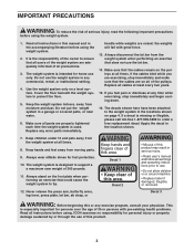
handle while weights are adequately informed of serious injury, read the following important precautions before using the weight system. 1. If a decal is used. Replace any time while exercising, stop immediately and make sure that the cables are on all of the pulleys. Make sure that could cause the weight system to the weight system in any exercise program, consult your physician. If you are properly tightened each time the weight system is missing or illegible, please call toll-free 1-877-992-5999 to support a a maximum user weight of this or any ...
handle while weights are adequately informed of serious injury, read the following important precautions before using the weight system. 1. If a decal is used. Replace any time while exercising, stop immediately and make sure that the cables are on all of the pulleys. Make sure that could cause the weight system to the weight system in any exercise program, consult your physician. If you are properly tightened each time the weight system is missing or illegible, please call toll-free 1-877-992-5999 to support a a maximum user weight of this or any ...
User Manual
Page 4
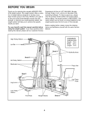
... number is to tone your body, build dramatic muscle size and strength, or improve your benefit, read this manual). If you for selecting the versatile WEIDER® PRO 3750 weight system. Mountain Time (excluding holidays). The weight system offers a selection of the body. Width: 64 in.
... number is to tone your body, build dramatic muscle size and strength, or improve your benefit, read this manual). If you for selecting the versatile WEIDER® PRO 3750 weight system. Mountain Time (excluding holidays). The weight system offers a selection of the body. Width: 64 in.
User Manual
Page 5
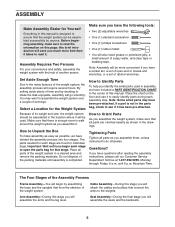
this stage you will save you much more convenient if you have a socket set, a set of open the parts bag for each assembly step. You may have questions after reading the assembly instructions, please call our Customer Service Department toll-free at 1-877-992-5999, Monday through Friday, 6 a.m. Note: Some small parts may want to see if it has been pre-attached. Because of its weight and size, the weight system should be assembled in the location where it to do otherwise. If you have been pre-attached. until assembly is designed to the many features of the weight system...
this stage you will save you much more convenient if you have a socket set, a set of open the parts bag for each assembly step. You may have questions after reading the assembly instructions, please call our Customer Service Department toll-free at 1-877-992-5999, Monday through Friday, 6 a.m. Note: Some small parts may want to see if it has been pre-attached. Because of its weight and size, the weight system should be assembled in the location where it to do otherwise. If you have been pre-attached. until assembly is designed to the many features of the weight system...
User Manual
Page 6
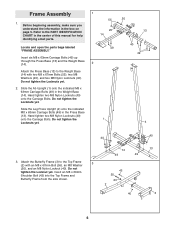
Do not tighten the Locknuts yet. 2. Slide the Ab Upright (1) onto the indicated M8 x 63mm Carriage Bolts (49) in the Press Base (13). Attach the Butterfly Frame (3) to the Top Frame 3 (2) with two M8 x 67mm Bolts (55), two M8 Washers (20), and two M8 Nylon Locknuts (40). Do not tighten the Locknuts yet. Slide the Leg Press Upright (4) onto the indicated M8 x 63mm Carriage Bolts (49) in the Weight Base (14). Insert an M8 x 69mm Shoulder Bolt (43) into the Top Frame and Butterfly Frame from the side shown. 14 49 49 43 55 20 2 40 40 13 3 6 Frame Assembly 1. Refer to the...
Do not tighten the Locknuts yet. 2. Slide the Ab Upright (1) onto the indicated M8 x 63mm Carriage Bolts (49) in the Press Base (13). Attach the Butterfly Frame (3) to the Top Frame 3 (2) with two M8 x 67mm Bolts (55), two M8 Washers (20), and two M8 Nylon Locknuts (40). Do not tighten the Locknuts yet. Slide the Leg Press Upright (4) onto the indicated M8 x 63mm Carriage Bolts (49) in the Weight Base (14). Insert an M8 x 69mm Shoulder Bolt (43) into the Top Frame and Butterfly Frame from the side shown. 14 49 49 43 55 20 2 40 40 13 3 6 Frame Assembly 1. Refer to the...
User Manual
Page 7
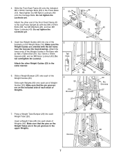
Do not tighten the Locknuts yet. Insert two Weight Guides (23) into each Weight Tube (25). Make sure that the pins on the Weight Tubes are in the pin grooves in the upper Weights. 23 23 7 25 26 90 90 Groove 7 Press a Weight Tube Bumper (26) into each stack of Weights. 14 69 6 90 Pin Grooves 67 90 Pin Grooves 27 27 7. Attach the other Weight Guides (23) in the Press Base (13). Do Hole 23 not overtighten the Locknut. Insert a Weight Tube (25) into one of the 5 brackets on the indicated side of each stack of Weights (90). Hand tighten two M8 Nylon Locknuts (40) ...
Do not tighten the Locknuts yet. Insert two Weight Guides (23) into each Weight Tube (25). Make sure that the pins on the Weight Tubes are in the pin grooves in the upper Weights. 23 23 7 25 26 90 90 Groove 7 Press a Weight Tube Bumper (26) into each stack of Weights. 14 69 6 90 Pin Grooves 67 90 Pin Grooves 27 27 7. Attach the other Weight Guides (23) in the Press Base (13). Do Hole 23 not overtighten the Locknut. Insert a Weight Tube (25) into one of the 5 brackets on the indicated side of each stack of Weights (90). Hand tighten two M8 Nylon Locknuts (40) ...
User Manual
Page 8
Attach the upper ends of the other set of Weight Guides (23) to the Top Frame (2) with the included grease. Attach the upper ends of one set of Weight Guides (23) to the Top Frame (2) in the same manner. Tighten the M8 Nylon Locknuts (40) used in the 8 Top Weights (24) with an M8 x 152mm Bolt (67), two 13mm x 19mm Spacers (69), and an M8 Nylon Locknut (40). Attach the Top Frame (2) to the Leg Press Upright (4) with two M8 x 67mm Bolts (55), two M8 Washers (20), and two M8 Nylon Locknuts (40). Do not tighten the Locknuts yet. 10. Slide a Top Weight onto each set ...
Attach the upper ends of the other set of Weight Guides (23) to the Top Frame (2) with the included grease. Attach the upper ends of one set of Weight Guides (23) to the Top Frame (2) in the same manner. Tighten the M8 Nylon Locknuts (40) used in the 8 Top Weights (24) with an M8 x 152mm Bolt (67), two 13mm x 19mm Spacers (69), and an M8 Nylon Locknut (40). Attach the Top Frame (2) to the Leg Press Upright (4) with two M8 x 67mm Bolts (55), two M8 Washers (20), and two M8 Nylon Locknuts (40). Do not tighten the Locknuts yet. 10. Slide a Top Weight onto each set ...
User Manual
Page 9
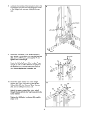
Lubricate the M10 x 80mm Bolt (71) with the Bolt and an M10 Nylon Locknut (42). Press a 25mm x 22mm Plastic Bushing (54) onto each welded spacer on the side shown. the Press Frame must be able to pivot easily. 8 9 53 42 72 Lubricate 13 71 14. Attach the Leg Press Arm (9) to the Adjustment Tube (10) with the Lock Pin (73). 12 73 10 11 9 13. Make sure that the high hole is on the Press Frame (12). Do not overtighten the Locknut; Attach the Leg Press Plate (11) to the Press Base (13) with grease. Note: This will be able to the Leg Press Arm (9) with ...
Lubricate the M10 x 80mm Bolt (71) with the Bolt and an M10 Nylon Locknut (42). Press a 25mm x 22mm Plastic Bushing (54) onto each welded spacer on the side shown. the Press Frame must be able to pivot easily. 8 9 53 42 72 Lubricate 13 71 14. Attach the Leg Press Arm (9) to the Adjustment Tube (10) with the Lock Pin (73). 12 73 10 11 9 13. Make sure that the high hole is on the Press Frame (12). Do not overtighten the Locknut; Attach the Leg Press Plate (11) to the Press Base (13) with grease. Note: This will be able to the Leg Press Arm (9) with ...
User Manual
Page 10
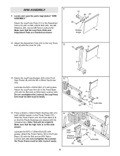
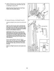
IMPORTANT NOTE: Before assembling the 25mm Retainers (45) used in this step, make sure that the teeth on the Retainers bend toward the Round Outer Cap, as shown in the inset drawing. Make sure that you will need to the Press Frame (12) in the same manner. 40 7 12 3 Lubricate Axle 5 Bracket 45 46 6 Axle 45 46 10 Make sure that the upper end of the Press 15 Frame (12) with the Right Fly Arm (5). Lubricate both axles on the Butterfly Frame (3). 15. Attach the other Press Arm (7) to order new Retainers. Tap two 25mm Retainers (45) and a 25mm Round Outer Cap (46)...
IMPORTANT NOTE: Before assembling the 25mm Retainers (45) used in this step, make sure that the teeth on the Retainers bend toward the Round Outer Cap, as shown in the inset drawing. Make sure that you will need to the Press Frame (12) in the same manner. 40 7 12 3 Lubricate Axle 5 Bracket 45 46 6 Axle 45 46 10 Make sure that the upper end of the Press 15 Frame (12) with the Right Fly Arm (5). Lubricate both axles on the Butterfly Frame (3). 15. Attach the other Press Arm (7) to order new Retainers. Tap two 25mm Retainers (45) and a 25mm Round Outer Cap (46)...
User Manual
Page 11
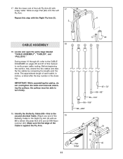
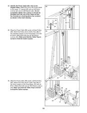
Locate and open the parts bags labeled "CABLE ASSEMBLY", "CABLES", and "PULLEYS." During steps 19 through 49, refer to the CABLE DIAGRAMS on pages 26 and 27 of this step with an M8 x 22mm Shoulder Bolt (51) and an M8 Nylon Locknut (40). the pulleys must be able to verify proper cable routing. Repeat this manual to turn freely. 19. IMPORTANT: While assembling the cables, do not overtighten the bolts and locknuts attaching the pulleys; Make sure the flat edge of each cable, in inches, is against the Fly Arm. 11 22 87-72" 89-82" 85-100" 86-109" 88-238" Flat Edge 51 89 5 ...
Locate and open the parts bags labeled "CABLE ASSEMBLY", "CABLES", and "PULLEYS." During steps 19 through 49, refer to the CABLE DIAGRAMS on pages 26 and 27 of this step with an M8 x 22mm Shoulder Bolt (51) and an M8 Nylon Locknut (40). the pulleys must be able to verify proper cable routing. Repeat this manual to turn freely. 19. IMPORTANT: While assembling the cables, do not overtighten the bolts and locknuts attaching the pulleys; Make sure the flat edge of each cable, in inches, is against the Fly Arm. 11 22 87-72" 89-82" 85-100" 86-109" 88-238" Flat Edge 51 89 5 ...
User Manual
Page 12
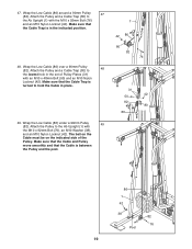
Wrap the Butterfly Cable (89) under a 90mm Pulley (82). Make sure that the Cable Trap is against the Fly Arm. 51 89 40 6 Flat Edge 12 Attach the Pulley and a Cable 22 Trap (80) to the other side of the Cable is positioned to the bracket on the Leg Press Upright (4) with an M10 x 48mm Bolt (50) and the M10 Nylon Locknut (42). Make sure the flat edge of the bracket on the Leg Press Upright (4) with an M8 x 22mm Shoulder Bolt (51) and an M8 Nylon Locknut (40). Wrap the Butterfly Cable (89) around a 90mm 20 Pulley (82) as shown. Attach the Pulley and a Cable Trap 21 (80...
Wrap the Butterfly Cable (89) under a 90mm Pulley (82). Make sure that the Cable Trap is against the Fly Arm. 51 89 40 6 Flat Edge 12 Attach the Pulley and a Cable 22 Trap (80) to the other side of the Cable is positioned to the bracket on the Leg Press Upright (4) with an M10 x 48mm Bolt (50) and the M10 Nylon Locknut (42). Make sure the flat edge of the bracket on the Leg Press Upright (4) with an M8 x 22mm Shoulder Bolt (51) and an M8 Nylon Locknut (40). Wrap the Butterfly Cable (89) around a 90mm 20 Pulley (82) as shown. Attach the Pulley and a Cable Trap 21 (80...
User Manual
Page 13
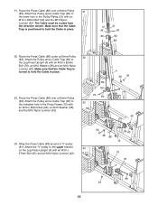
Attach the Rear Cable to the Top Frame (2) with 26 an M10 x 48mm Bolt (50) and an M10 Nylon Locknut (42). Attach the Pulley to the Top Frame with an M8 Nylon Locknut (40) and an M8 27 Washer (20). it should be routed from the Top Frame (2). 24. cated M8 Nylon Locknut (40). Identify the Rear Cable (87)-this is against the Top Frame. 43 2 87 Loosen-40 Retighten the indicated M8 Nylon Locknut (40). 25. Wrap the Rear Cable (87) under a 90mm Pulley (82). Attach the Small "U"-bracket (32) to a Small "U"-bracket (32) with the M8 x 69mm Shoulder Bolt (43) and an ...
Attach the Rear Cable to the Top Frame (2) with 26 an M10 x 48mm Bolt (50) and an M10 Nylon Locknut (42). Attach the Pulley to the Top Frame with an M8 Nylon Locknut (40) and an M8 27 Washer (20). it should be routed from the Top Frame (2). 24. cated M8 Nylon Locknut (40). Identify the Rear Cable (87)-this is against the Top Frame. 43 2 87 Loosen-40 Retighten the indicated M8 Nylon Locknut (40). 25. Wrap the Rear Cable (87) under a 90mm Pulley (82). Attach the Small "U"-bracket (32) to a Small "U"-bracket (32) with the M8 x 69mm Shoulder Bolt (43) and an ...
User Manual
Page 14
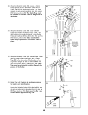
Attach the end of the Cable so that the Cable Trap is the 28 longest Cable. Make sure that the Cable Trap is turned to hold the Cable in place. 88 80 42 82 30. Wrap the Press Cable (88) under a 90mm Pulley (82). It should be threaded onto the end of the Press Cable to the Large "U"-bracket (84) with an M10 x 48mm Bolt (50) and an M10 Nylon Locknut (42). Attach the Pulley and a Cable Trap (80) to 29 the indicated bracket on the Press Base (13) with an M8 Nylon Locknut (40) and an M8 Washer (20). Attach the Pulley and a Cable Trap (80) to 30 the other bracket on the ...
Attach the end of the Cable so that the Cable Trap is the 28 longest Cable. Make sure that the Cable Trap is turned to hold the Cable in place. 88 80 42 82 30. Wrap the Press Cable (88) under a 90mm Pulley (82). It should be threaded onto the end of the Press Cable to the Large "U"-bracket (84) with an M10 x 48mm Bolt (50) and an M10 Nylon Locknut (42). Attach the Pulley and a Cable Trap (80) to 29 the indicated bracket on the Press Base (13) with an M8 Nylon Locknut (40) and an M8 Washer (20). Attach the Pulley and a Cable Trap (80) to 30 the other bracket on the ...
User Manual
Page 15
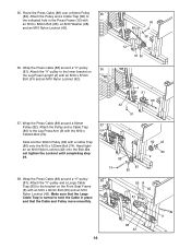
Make sure that the Cable Trap is positioned to hold the Cable in the Press Frame (12) with an M10 x 48mm Bolt (50) and the M10 Nylon Locknut (42). Attach the Pulley and a Cable Trap (80) to the lower hole in place. 33. The Cable must be routed from the direction shown. Route the Press Cable (88) under a 90mm Pulley 32 (82). Route the Press Cable (88) over a 90mm Pulley 31 (82). Attach the Pulley and a Cable Trap (80) to the indicated hole in place. 31 31 42 50 80 82 88 32. Route the Press Cable (88) over a 90mm Pulley (82). Wrap the Press Cable (88) around ...
Make sure that the Cable Trap is positioned to hold the Cable in the Press Frame (12) with an M10 x 48mm Bolt (50) and the M10 Nylon Locknut (42). Attach the Pulley and a Cable Trap (80) to the lower hole in place. 33. The Cable must be routed from the direction shown. Route the Press Cable (88) under a 90mm Pulley 32 (82). Route the Press Cable (88) over a 90mm Pulley 31 (82). Attach the Pulley and a Cable Trap (80) to the indicated hole in place. 31 31 42 50 80 82 88 32. Route the Press Cable (88) over a 90mm Pulley (82). Wrap the Press Cable (88) around ...
User Manual
Page 16
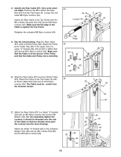
Attach the "V"-pulley to the bracket on the Leg Press Upright (4) with an M10 x 57mm Bolt (91) and an M10 Nylon Locknut (42). 37. Wrap the Press Cable (88) around a "V"-pulley (81). Route the Press Cable (88) over a 90mm Pulley 35 (82). Attach the Pulley and a Cable Trap (80) to hold the Cable in the Press Frame (12) with an M10 x 60mm Bolt (65) and an M10 Nylon Locknut (42). Hand tighten an M10 Nylon Locknut (42) onto the Bolt. Wrap the Press Cable (88) around a 90mm Pulley (82). Make sure that the Cable and Pulley move smoothly. 36 4 81 88 42 91 37 82 42 88 74...
Attach the "V"-pulley to the bracket on the Leg Press Upright (4) with an M10 x 57mm Bolt (91) and an M10 Nylon Locknut (42). 37. Wrap the Press Cable (88) around a "V"-pulley (81). Route the Press Cable (88) over a 90mm Pulley 35 (82). Attach the Pulley and a Cable Trap (80) to hold the Cable in the Press Frame (12) with an M10 x 60mm Bolt (65) and an M10 Nylon Locknut (42). Hand tighten an M10 Nylon Locknut (42) onto the Bolt. Wrap the Press Cable (88) around a 90mm Pulley (82). Make sure that the Cable and Pulley move smoothly. 36 4 81 88 42 91 37 82 42 88 74...
User Manual
Page 17
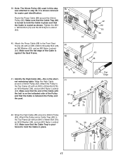
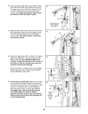
Make sure that the Cable is posi- Tighten the M10 x 120mm Bolt (74) and the M10 Nylon Locknut (42). 74 40. Make sure the flat edge of the Pulley and that the Cable Trap (80) is turned to hold the Cable in place. 76 38 2 80 82 42 85 17 Identify the High Cable (85)-this step 39 was attached in place and that the Cable Trap is between the Pulley and the post. 40 20 41 2 38 42 82 Post 85 76 9 42 82 80 88 43 88 Flat Edge 42. Route the Press Cable (88) around a 90mm Pulley (82). Attach the Press Cable (88) to the Top Frame (2) with the ball is on the ...
Make sure that the Cable is posi- Tighten the M10 x 120mm Bolt (74) and the M10 Nylon Locknut (42). 74 40. Make sure the flat edge of the Pulley and that the Cable Trap (80) is turned to hold the Cable in place. 76 38 2 80 82 42 85 17 Identify the High Cable (85)-this step 39 was attached in place and that the Cable Trap is between the Pulley and the post. 40 20 41 2 38 42 82 Post 85 76 9 42 82 80 88 43 88 Flat Edge 42. Route the Press Cable (88) around a 90mm Pulley (82). Attach the Press Cable (88) to the Top Frame (2) with the ball is on the ...
User Manual
Page 18
Wrap the High Cable (85) around a 90mm Pulley (82). Do not completely tighten the Locknut. Wrap the Low Cable over a 90mm Pulley (82). Route the High Cable (85) under a 90mm Pulley (82). the Pulley should be down 31 44 42 2 50 82 85 45. The Cable must be on this 86 side 95 94 38 1 18 Attach the Pulley and both Pulley Covers (94) to the single hole end of the Cable so that two threads show past the Locknut (see the inset drawing). Make sure that the Pulley Covers are turned so the wide tabs are on the indicated side. 45 32 32 68 85 20 40 85 40 20 40 25 46 ...
Wrap the High Cable (85) around a 90mm Pulley (82). Do not completely tighten the Locknut. Wrap the Low Cable over a 90mm Pulley (82). Route the High Cable (85) under a 90mm Pulley (82). the Pulley should be down 31 44 42 2 50 82 85 45. The Cable must be on this 86 side 95 94 38 1 18 Attach the Pulley and both Pulley Covers (94) to the single hole end of the Cable so that two threads show past the Locknut (see the inset drawing). Make sure that the Pulley Covers are turned so the wide tabs are on the indicated side. 45 32 32 68 85 20 40 85 40 20 40 25 46 ...
User Manual
Page 19
The ball on the Cable must be on the indicated side of Pulley Plates (31) with the M10 x 92mm Bolt (76), an M10 Washer (38), and an M10 Nylon Locknut (42). Attach the Pulley to hold the Cable in place. 49. Make sure that the Cable and Pulley move smoothly and that the Cable Trap is turned to the Ab Upright (1) with an M10 x 48mm Bolt (50) and an M10 Nylon Locknut (42). Wrap the Low Cable (86) over a 90mm Pulley (82). Attach the Pulley and a Cable Trap (80) to the Ab Upright (1) with the M10 x 92mm Bolt (76) and an M10 Nylon Locknut (42). 47. Attach the Pulley and...
The ball on the Cable must be on the indicated side of Pulley Plates (31) with the M10 x 92mm Bolt (76), an M10 Washer (38), and an M10 Nylon Locknut (42). Attach the Pulley to hold the Cable in place. 49. Make sure that the Cable and Pulley move smoothly and that the Cable Trap is turned to the Ab Upright (1) with an M10 x 48mm Bolt (50) and an M10 Nylon Locknut (42). Wrap the Low Cable (86) over a 90mm Pulley (82). Attach the Pulley and a Cable Trap (80) to the Ab Upright (1) with the M10 x 92mm Bolt (76) and an M10 Nylon Locknut (42). 47. Attach the Pulley and...
User Manual
Page 20
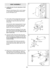
Thread an M6 Nylon Locknut (44) and an M6 Washer (37) onto the Carriage Bolt. Tighten the M6 Nylon Locknut (44). 52. Attach the Seat Plate to a Seat (17) with an M8 x 70mm Carriage Bolt (77) and the Seat Knob (30). 30 16 1 77 Post Slot 20 Insert the M6 x 52mm Carriage Bolt (61) through the center hole in a Seat Plate (41). Do not overtighten the Locknut; Tighten an M10 Nylon Locknut (42) and an M10 Washer (38) onto the Eyebolt. 51 17 61 41 59 16 37 63 44 52 40 15 38 42 16 Lubricate 62 79 53. Attach the 53 Rear Seat Frame to the Rear Seat Frame (16) with grease. ...
Thread an M6 Nylon Locknut (44) and an M6 Washer (37) onto the Carriage Bolt. Tighten the M6 Nylon Locknut (44). 52. Attach the Seat Plate to a Seat (17) with an M8 x 70mm Carriage Bolt (77) and the Seat Knob (30). 30 16 1 77 Post Slot 20 Insert the M6 x 52mm Carriage Bolt (61) through the center hole in a Seat Plate (41). Do not overtighten the Locknut; Tighten an M10 Nylon Locknut (42) and an M10 Washer (38) onto the Eyebolt. 51 17 61 41 59 16 37 63 44 52 40 15 38 42 16 Lubricate 62 79 53. Attach the 53 Rear Seat Frame to the Rear Seat Frame (16) with grease. ...