

English Manual
Page 2
Remove the PART IDENTIFICATION CHART and the PART LIST/EXPLODED DRAWING before beginning assembly. TABLE OF CONTENTS IMPORTANT PRECAUTIONS 3 BEFORE YOU BEGIN 4 ASSEMBLY 5 ADJUSTMENTS 22 WEIGHT RESISTANCE CHART 24 TROUBLESHOOTING 25 CABLE DIAGRAMS 26 ORDERING REPLACEMENT PARTS Back Cover LIMITED WARRANTY Back Cover Note: A PART IDENTIFICATION CHART and a PART LIST/EXPLODED DRAWING are attached in the center of ICON Health & Fitness, Inc. 2 WEIDER is a registered trademark of this manual.
Remove the PART IDENTIFICATION CHART and the PART LIST/EXPLODED DRAWING before beginning assembly. TABLE OF CONTENTS IMPORTANT PRECAUTIONS 3 BEFORE YOU BEGIN 4 ASSEMBLY 5 ADJUSTMENTS 22 WEIGHT RESISTANCE CHART 24 TROUBLESHOOTING 25 CABLE DIAGRAMS 26 ORDERING REPLACEMENT PARTS Back Cover LIMITED WARRANTY Back Cover Note: A PART IDENTIFICATION CHART and a PART LIST/EXPLODED DRAWING are attached in the center of ICON Health & Fitness, Inc. 2 WEIDER is a registered trademark of this manual.
English Manual
Page 4
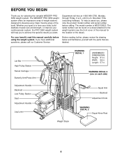
... your body, build dramatic muscle size and strength, or improve your cardiovascular system, the PRO 3650 weight system will help us assist you, please note the product model number and serial ...ASSEMBLED DIMENSIONS: Height: 81 in . To help you to achieve the specific results you have additional questions, please call our Customer Service Before reading further, please review the drawing below and familiarize yourself with the parts that are labeled. For your goal is WESY39523. The WEIDER® PRO 3650...manual for selecting the versatile WEIDER® PRO 3650 weight system.
... your body, build dramatic muscle size and strength, or improve your cardiovascular system, the PRO 3650 weight system will help us assist you, please note the product model number and serial ...ASSEMBLED DIMENSIONS: Height: 81 in . To help you to achieve the specific results you have additional questions, please call our Customer Service Before reading further, please review the drawing below and familiarize yourself with the parts that are labeled. For your goal is WESY39523. The WEIDER® PRO 3650...manual for selecting the versatile WEIDER® PRO 3650 weight system.
English Manual
Page 5
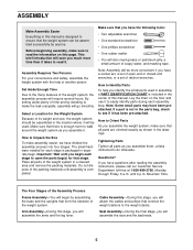
... packing materials. The small hardware needed for each stage to read the information on the floor and use it to make assembly easier, we have divided the assembly process into four stages. Lay the chart on this page. If you have been preattached. Place all parts are oriented ...exactly as shown in the drawings. Note: Some small parts may have questions after reading the assembly instructions, please call our Customer Service Department toll-free at 1-800-999-3756, Monday through Friday, 6 a.m. How to see if it has ...
... packing materials. The small hardware needed for each stage to read the information on the floor and use it to make assembly easier, we have divided the assembly process into four stages. Lay the chart on this page. If you have been preattached. Place all parts are oriented ...exactly as shown in the drawings. Note: Some small parts may have questions after reading the assembly instructions, please call our Customer Service Department toll-free at 1-800-999-3756, Monday through Friday, 6 a.m. How to see if it has ...
English Manual
Page 6
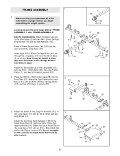
...the Foot Plate (53). Press two 50mm x 75mm Inner Caps (58) into the open the parts bags labeled "FRAME ASSEMBLY 1" and "FRAME ASSEMBLY 2." Attach the tether on page 5 before you begin assembling the weight system. 2 24 120 14 Locate and open end of the information on the Long Pin w/Tether (112) ...Attach the Squat Knee Rest to the Short Base (2) with four M4 x 20mm Selftapping Screws (14). Do not overtighten the Locknut; ping Screw (14). FRAME ASSEMBLY 1 1. Attach the Foot Plate to pivot. 6 14 101 87 112 96 41 108 14 108 108 14 Insert eight M10 x 65mm Carriage Bolts (110)...
...the Foot Plate (53). Press two 50mm x 75mm Inner Caps (58) into the open the parts bags labeled "FRAME ASSEMBLY 1" and "FRAME ASSEMBLY 2." Attach the tether on page 5 before you begin assembling the weight system. 2 24 120 14 Locate and open end of the information on the Long Pin w/Tether (112) ...Attach the Squat Knee Rest to the Short Base (2) with four M4 x 20mm Selftapping Screws (14). Do not overtighten the Locknut; ping Screw (14). FRAME ASSEMBLY 1 1. Attach the Foot Plate to pivot. 6 14 101 87 112 96 41 108 14 108 108 14 Insert eight M10 x 65mm Carriage Bolts (110)...
English Manual
Page 9
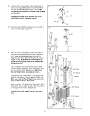
... 39 10. Make sure that the Weight Tube is facing downward. Apply decals with an M8 x 85mm Bolt (94) and an M8 Nylon Locknut (34). Assemble the other three Rollers (39) to the ten Weights (44). Attach a Roller (39) between the indicated set of a Weight Tube (43). Do not overtighten the... of the Weights (44). Insert the Weight Tube into the indicated bracket on the Long Base (101). Make sure that the Weights are facing downward. 9. Assemble the other weight stack in a Top Weight (45). Slide the Top Weight onto the Weight Guides (42).
... 39 10. Make sure that the Weight Tube is facing downward. Apply decals with an M8 x 85mm Bolt (94) and an M8 Nylon Locknut (34). Assemble the other three Rollers (39) to the ten Weights (44). Attach a Roller (39) between the indicated set of a Weight Tube (43). Do not overtighten the... of the Weights (44). Insert the Weight Tube into the indicated bracket on the Long Base (101). Make sure that the Weights are facing downward. 9. Assemble the other weight stack in a Top Weight (45). Slide the Top Weight onto the Weight Guides (42).
English Manual
Page 10
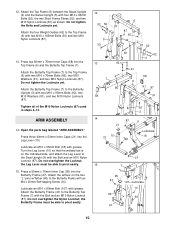
...). Lubricate an M10 x 65mm Bolt (18) with grease. Lubricate an M10 x 80mm Bolt (107) with grease. Do not tighten the Bolts and Locknuts yet. ARM ASSEMBLY 14. Attach the Butterfly Frame (47) to pivot easily. 15. Attach the Top Frame (6) between the Squat Upright (4) and the Swivel Upright (5) with the Bolt... Locknut; Attach the four Weight Guides (42) to the Top Frame (6) with an M4 x 20mm Self-tapping Screw (14). Open the parts bag labeled "ARM ASSEMBLY." Press three 40mm x 50mm Inner Caps (21) into the Leg Lever (10).
...). Lubricate an M10 x 65mm Bolt (18) with grease. Lubricate an M10 x 80mm Bolt (107) with grease. Do not tighten the Bolts and Locknuts yet. ARM ASSEMBLY 14. Attach the Butterfly Frame (47) to pivot easily. 15. Attach the Top Frame (6) between the Squat Upright (4) and the Swivel Upright (5) with the Bolt... Locknut; Attach the four Weight Guides (42) to the Top Frame (6) with an M4 x 20mm Self-tapping Screw (14). Open the parts bag labeled "ARM ASSEMBLY." Press three 40mm x 50mm Inner Caps (21) into the Leg Lever (10).
English Manual
Page 11
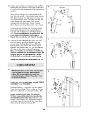
...). 16 26 51 54 Lubricate 100 70 87 21 29 25 28 27 17 104 26 56 91 57 57 91 87 47 25 CABLE ASSEMBLY 18. Attach two Pulleys to the Butterfly Frame (47) with grease. Wet the lower end of two Plastic Washers (56) with the Bolt, the two... the Swivel Cage (76) with soapy water. Do not overtighten the bolts and nuts attaching the pulleys. Locate and open the parts bags labeled "CABLE ASSEMBLY" and "PULLEYS." 78 74 30 87 Lubricate the M10 x 165mm Bolt (30) with the lower end of the Plastic Washers are fitted over the welded...
...). 16 26 51 54 Lubricate 100 70 87 21 29 25 28 27 17 104 26 56 91 57 57 91 87 47 25 CABLE ASSEMBLY 18. Attach two Pulleys to the Butterfly Frame (47) with grease. Wet the lower end of two Plastic Washers (56) with the Bolt, the two... the Swivel Cage (76) with soapy water. Do not overtighten the bolts and nuts attaching the pulleys. Locate and open the parts bags labeled "CABLE ASSEMBLY" and "PULLEYS." 78 74 30 87 Lubricate the M10 x 165mm Bolt (30) with the lower end of the Plastic Washers are fitted over the welded...
English Manual
Page 19
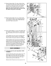
...) a few inches over a 115mm Pulley 54 (119). Make sure that the small pin on the weight stack. Locate and open the parts bag labeled "SEAT ASSEMBLY." 53. Wrap the Squat Cable (73) under the Top Weight. Thread a M12 Nut (118) halfway onto the end of the groove under a 90mm Pulley 53...) and make sure that the Cable Trap is inside of the Squat Cable (73). Then, tighten the M12 Nut (118) against the 50mm Washer (1). SEAT ASSEMBLY 56. Slide the two Knee Pads (19) onto the Pad Tube as shown.
...) a few inches over a 115mm Pulley 54 (119). Make sure that the small pin on the weight stack. Locate and open the parts bag labeled "SEAT ASSEMBLY." 53. Wrap the Squat Cable (73) under the Top Weight. Thread a M12 Nut (118) halfway onto the end of the groove under a 90mm Pulley 53...) and make sure that the Cable Trap is inside of the Squat Cable (73). Then, tighten the M12 Nut (118) against the 50mm Washer (1). SEAT ASSEMBLY 56. Slide the two Knee Pads (19) onto the Pad Tube as shown.

English Manual
Page 26
The cable diagrams on this page and the following page show the routes of the cables. IMPORTANT: If the cables have been assembled correctly. Cable Identification Chart Butterfly Cable (69)-1475mm Swivel Low Cable (72)-5207mm Squat Cable (73)-4425mm Swivel High Cable (74)-3213mm Leg Lever Cable (...
The cable diagrams on this page and the following page show the routes of the cables. IMPORTANT: If the cables have been assembled correctly. Cable Identification Chart Butterfly Cable (69)-1475mm Swivel Low Cable (72)-5207mm Squat Cable (73)-4425mm Swivel High Cable (74)-3213mm Leg Lever Cable (...


