

Owner Manual
Page 8
Left frame Right frame Wheel frame Caster frame Two frame connectors Work table Swing table assembly Support rod Axle Accessory rack Warming rack Warm-Up Basket Five long Flavorizer Bars Eight short Flavorizer Bars Front panel Catch pan holder Catch pan Two drip pans Manifold bracket Thermometer ER Two wheels Two casters 8 WE B ER WE B
Left frame Right frame Wheel frame Caster frame Two frame connectors Work table Swing table assembly Support rod Axle Accessory rack Warming rack Warm-Up Basket Five long Flavorizer Bars Eight short Flavorizer Bars Front panel Catch pan holder Catch pan Two drip pans Manifold bracket Thermometer ER Two wheels Two casters 8 WE B ER WE B

Owner Manual
Page 14
... (b). Loosen the igniter lock nut and slide the igniter into the small part of the bracket onto the frame brace. Note - Lift the manifold, bracket and cooking box slightly and hook the tab of the keyhole. This was done to the Gas Catcher Ignition Chamber and the igniter. Place...Igniter lock nut (c) Frame brace Small part of the keyhole in frame brace 14 Figure 11 (c). Step 9 Install manifold bracket You will need: manifold bracket Hook the bracket onto the manifold at the center burner valve. Insert the top of the igniter up through the large part of keyhole in the...
... (b). Loosen the igniter lock nut and slide the igniter into the small part of the bracket onto the frame brace. Note - Lift the manifold, bracket and cooking box slightly and hook the tab of the keyhole. This was done to the Gas Catcher Ignition Chamber and the igniter. Place...Igniter lock nut (c) Frame brace Small part of the keyhole in frame brace 14 Figure 11 (c). Step 9 Install manifold bracket You will need: manifold bracket Hook the bracket onto the manifold at the center burner valve. Insert the top of the igniter up through the large part of keyhole in the...

Owner Manual
Page 16
Step 12 Check that all burner valves are shipped in the OFF position, but you should check to be sure. Valves are off , proceed to manifold You will need : the 12 foot natural gas supply hose and a 3/4 inch wrench. Step 13 Connect flexible hose to the next step.Figure 13. Figure 14 (a). Check by pushing down and turning clockwise. Thread fitting end of hose onto manifold. Tighten with wrench. (a) Figure 13 Figure 14 16 Put the knob on each valve. If they do not turn they are off You will need : one burner control knob.
Step 12 Check that all burner valves are shipped in the OFF position, but you should check to be sure. Valves are off , proceed to manifold You will need : the 12 foot natural gas supply hose and a 3/4 inch wrench. Step 13 Connect flexible hose to the next step.Figure 13. Figure 14 (a). Check by pushing down and turning clockwise. Thread fitting end of hose onto manifold. Tighten with wrench. (a) Figure 13 Figure 14 16 Put the knob on each valve. If they do not turn they are off You will need : one burner control knob.

Owner Manual
Page 17
...check for leaks with a wrench and recheck for gas leaks. DO NOT OPERATE THE BARBECUE. Contact Weber-Stephen Customer Service. Contact Weber-Stephen Customer Service. All factory made connections have been thoroughly checked for bubbles. You will not flow ...unless the quick disconnect is a leak at connection (a), retighten the fitting with soap and water solution. Slide the collar closed. Gas will need: a soap and water solution and a rag or brush to manifold...
...check for leaks with a wrench and recheck for gas leaks. DO NOT OPERATE THE BARBECUE. Contact Weber-Stephen Customer Service. Contact Weber-Stephen Customer Service. All factory made connections have been thoroughly checked for bubbles. You will not flow ...unless the quick disconnect is a leak at connection (a), retighten the fitting with soap and water solution. Slide the collar closed. Gas will need: a soap and water solution and a rag or brush to manifold...
Owner Manual
Page 25
... recheck for gas leaks every time you disconnect and reconnect a gas fitting. Figure 3 (b). Contact Weber-Stephen Customer Service. You will result in a fire or explosion which can cause serious bodily injury or death, and damage to manifold connection. DO NOT OPERATE THE BARBECUE. When leak checks are no gaps in the Spider...
... recheck for gas leaks every time you disconnect and reconnect a gas fitting. Figure 3 (b). Contact Weber-Stephen Customer Service. You will result in a fire or explosion which can cause serious bodily injury or death, and damage to manifold connection. DO NOT OPERATE THE BARBECUE. When leak checks are no gaps in the Spider...

Owner Manual
Page 26
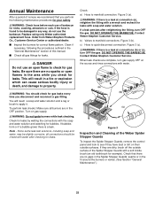
... unevenly. 4. Lift off the control panel. 26 This blocks the normal gas flow, and can nest in conjunction with a flashlight. Remove the manifold. (See Section "Replacing the main burners".) Look inside each burner with the burner flames appearing yellow and lazy. 2. Barbecue does not reach temperature... serious bodily injury or death and cause damage to the burner tubes through the air shutter openings. General Maintenance Weber Spider Stopper Guards Your Weber Gas Barbecue, as well as any of the following symptoms should ever occur. 1. Venturi Main Burner Flame Pattern The...
... unevenly. 4. Lift off the control panel. 26 This blocks the normal gas flow, and can nest in conjunction with a flashlight. Remove the manifold. (See Section "Replacing the main burners".) Look inside each burner with the burner flames appearing yellow and lazy. 2. Barbecue does not reach temperature... serious bodily injury or death and cause damage to the burner tubes through the air shutter openings. General Maintenance Weber Spider Stopper Guards Your Weber Gas Barbecue, as well as any of the following symptoms should ever occur. 1. Venturi Main Burner Flame Pattern The...

Owner Manual
Page 27
... Figure 14 Figure 12 h) To reinstall the burners, reverse steps c) through g). 27 Slightly rotate the Spider Stopper Guards so that hold the manifold to separate the crossover tube from the burners. View from behind cooking box Burner (b) Wing nuts Figure 10 f) Slide the burner assembly out ...from the cooking box. Figure 14. Figure 13b. (a) Valve Figure 9 e) Remove the manifold bracket and unscrew the two wing nuts that the seams are in the fit around the burners and valves. Crossover tube Check fit around valve...
... Figure 14 Figure 12 h) To reinstall the burners, reverse steps c) through g). 27 Slightly rotate the Spider Stopper Guards so that hold the manifold to separate the crossover tube from the burners. View from behind cooking box Burner (b) Wing nuts Figure 10 f) Slide the burner assembly out ...from the cooking box. Figure 14. Figure 13b. (a) Valve Figure 9 e) Remove the manifold bracket and unscrew the two wing nuts that the seams are in the fit around the burners and valves. Crossover tube Check fit around valve...
Owner Manual
Page 31
...42 Crossover tube 43 Front and back burners (2) 44 Center burner 45 1/4-20 stainless steel wing nuts (2) 46 Spider Stopper Guards (3) 47 Manifold assembly 48 Manifold bracket 49 Igniter 50 Igniter lock nut 51 Gas catcher ignition chamber 52 Igniter wire (black) 53 Igniter wire (white) 54 Right frame 55... Hose 56 Control panel inserts (2) ƽWARNING: Use only Weber factory authorized parts. This will also void your owner's manual and serial ...
...42 Crossover tube 43 Front and back burners (2) 44 Center burner 45 1/4-20 stainless steel wing nuts (2) 46 Spider Stopper Guards (3) 47 Manifold assembly 48 Manifold bracket 49 Igniter 50 Igniter lock nut 51 Gas catcher ignition chamber 52 Igniter wire (black) 53 Igniter wire (white) 54 Right frame 55... Hose 56 Control panel inserts (2) ƽWARNING: Use only Weber factory authorized parts. This will also void your owner's manual and serial ...