

Owner Manual
Page 8
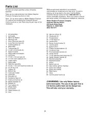
Left frame Right frame Wheel frame Caster frame Two frame connectors Work table Swing table assembly Left hand slide bar Axle Two accessory trays Warming rack Warm-Up Basket Five long Flavorizer Bars Eight short Flavorizer Bars Front panel Catch pan holder Catch pan Two drip pans Manifold bracket Thermometer ER Two wheels Two casters Spacer bracket 8 WE B ER WE B
Left frame Right frame Wheel frame Caster frame Two frame connectors Work table Swing table assembly Left hand slide bar Axle Two accessory trays Warming rack Warm-Up Basket Five long Flavorizer Bars Eight short Flavorizer Bars Front panel Catch pan holder Catch pan Two drip pans Manifold bracket Thermometer ER Two wheels Two casters Spacer bracket 8 WE B ER WE B

Owner Manual
Page 14
...11. Figure 10. Loosen the igniter lock nut and slide the igniter into the small part of the keyhole in the frame brace. Frame brace Manifold bracket Step 10 Install igniter Note - Figure 11 (c). Note - The igniter wires are already attached to factory test the ignition system. Insert the top...This was done to the Gas Catcher Ignition Chamber and the igniter. Figure 11 (b). The igniter lock nut is on the igniter. Lift the manifold, bracket and cooking box slightly and hook the tab of keyhole in frame brace Igniter lock nut (c) Frame brace Small part of the bracket onto...
...11. Figure 10. Loosen the igniter lock nut and slide the igniter into the small part of the keyhole in the frame brace. Frame brace Manifold bracket Step 10 Install igniter Note - Figure 11 (c). Note - The igniter wires are already attached to factory test the ignition system. Insert the top...This was done to the Gas Catcher Ignition Chamber and the igniter. Figure 11 (b). The igniter lock nut is on the igniter. Lift the manifold, bracket and cooking box slightly and hook the tab of keyhole in frame brace Igniter lock nut (c) Frame brace Small part of the bracket onto...

Owner Manual
Page 16
Step 12 Check that all burner valves are shipped in the OFF position, but you should check to be sure. Check by pushing down and turning clockwise. Thread fitting end of hose onto manifold. Valves are off , proceed to manifold You will need : the 12 foot natural gas supply hose and a 3/4 inch wrench. Step 13 Connect flexible hose to the next step.Figure 13. Put the knob on each valve. Tighten with wrench. (a) Figure 13 Figure 14 16 If they do not turn they are off You will need : one burner control knob. Figure 14 (a).
Step 12 Check that all burner valves are shipped in the OFF position, but you should check to be sure. Check by pushing down and turning clockwise. Thread fitting end of hose onto manifold. Valves are off , proceed to manifold You will need : the 12 foot natural gas supply hose and a 3/4 inch wrench. Step 13 Connect flexible hose to the next step.Figure 13. Put the knob on each valve. Tighten with wrench. (a) Figure 13 Figure 14 16 If they do not turn they are off You will need : one burner control knob. Figure 14 (a).

Owner Manual
Page 17
... house wall Check: a) Hose to check for gas leaks. Figure 16 (b). Figure 16 (c). ƽWARNING: If there is a leak. Contact Weber-Stephen Customer Service. If bubbles form or if a bubble grows there is a leak at the source and rinse connections with the soap and water ...leaks before using your barbecue was dealer or store assembled. If it . Contact Weber-Stephen Customer Service. c) Hose to manifold connections. Figure 15 (b). When leak checks are no sparks or open flame to manifold connection. To perform leak checks: Slide back the collar of the hose into ...
... house wall Check: a) Hose to check for gas leaks. Figure 16 (b). Figure 16 (c). ƽWARNING: If there is a leak. Contact Weber-Stephen Customer Service. If bubbles form or if a bubble grows there is a leak at the source and rinse connections with the soap and water ...leaks before using your barbecue was dealer or store assembled. If it . Contact Weber-Stephen Customer Service. c) Hose to manifold connections. Figure 15 (b). When leak checks are no sparks or open flame to manifold connection. To perform leak checks: Slide back the collar of the hose into ...
Owner Manual
Page 25
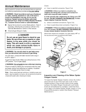
...is a leak. Contact Weber-Stephen Customer Service. Be sure there are dirty, brush off the outside surfaces. You will result in a fire or explosion which can cause serious bodily injury or death, and damage to check for leaks. Check: a) Hose to manifold connections. If they have ... at connections (b) or (c), turn gas supply OFF at connection (a), retighten the fitting with water. (a) (b) (c) Figure 3 Inspection and Cleaning of the Weber Spider Stopper Guards To inspect the Spider Stopper Guards, remove the control panel and look to see if they are no gaps in the Spider...
...is a leak. Contact Weber-Stephen Customer Service. Be sure there are dirty, brush off the outside surfaces. You will result in a fire or explosion which can cause serious bodily injury or death, and damage to check for leaks. Check: a) Hose to manifold connections. If they have ... at connections (b) or (c), turn gas supply OFF at connection (a), retighten the fitting with water. (a) (b) (c) Figure 3 Inspection and Cleaning of the Weber Spider Stopper Guards To inspect the Spider Stopper Guards, remove the control panel and look to see if they are no gaps in the Spider...

Owner Manual
Page 26
... and clean the Spider Stopper Guards if any outdoor gas appliance, is to clean outside of burners. Replacing Main Burners a) Your Weber Gas Barbecue must be uniform the length of the burner tube, follow the burner cleaning procedures. The correct flame pattern is factory installed... Figure 8. This is a target for the correct air and gas mixture. Tips occasionally yellowish Burner inside each burner with a flashlight. Remove the manifold. (See Section "Replacing the main burners".) Look inside cooking box Light blue Flames Figure 6 Dark blue If the flames do not ignite. ...
... and clean the Spider Stopper Guards if any outdoor gas appliance, is to clean outside of burners. Replacing Main Burners a) Your Weber Gas Barbecue must be uniform the length of the burner tube, follow the burner cleaning procedures. The correct flame pattern is factory installed... Figure 8. This is a target for the correct air and gas mixture. Tips occasionally yellowish Burner inside each burner with a flashlight. Remove the manifold. (See Section "Replacing the main burners".) Look inside cooking box Light blue Flames Figure 6 Dark blue If the flames do not ignite. ...

Owner Manual
Page 27
...445;CAUTION: The burner openings must be no gaps in the seams or in line with the Venturi fins. Figure 13b. (a) Valve Figure 9 e) Remove the manifold bracket and unscrew the two wing nuts that the seams are in the fit around burner Figure 14 Figure 12 27 Slightly rotate the Spider... Stopper Guards so that hold the manifold to separate the crossover tube from the cooking box. Figure 12. Remove the burners from the burners. View from behind cooking box Burner (b)...
...445;CAUTION: The burner openings must be no gaps in the seams or in line with the Venturi fins. Figure 13b. (a) Valve Figure 9 e) Remove the manifold bracket and unscrew the two wing nuts that the seams are in the fit around burner Figure 14 Figure 12 27 Slightly rotate the Spider... Stopper Guards so that hold the manifold to separate the crossover tube from the cooking box. Figure 12. Remove the burners from the burners. View from behind cooking box Burner (b)...
Owner Manual
Page 31
... tube 45 Front and back burners (2) 46 Center burner 47 1/4-20 stainless steel wing nuts (2) 48 Spider Stopper Guards (3) 49 Manifold assembly 50 Manifold bracket 51 Igniter 52 Igniter lock nut 53 Gas catcher ignition chamber 54 Igniter wire (black) 55 Igniter wire (white) 56 Right... frame 57 Hose 58 Control panel inserts (2) ƽWARNING: Use only Weber factory authorized parts. If a part is not factory authorized can be ordered directly from Weber...
... tube 45 Front and back burners (2) 46 Center burner 47 1/4-20 stainless steel wing nuts (2) 48 Spider Stopper Guards (3) 49 Manifold assembly 50 Manifold bracket 51 Igniter 52 Igniter lock nut 53 Gas catcher ignition chamber 54 Igniter wire (black) 55 Igniter wire (white) 56 Right... frame 57 Hose 58 Control panel inserts (2) ƽWARNING: Use only Weber factory authorized parts. If a part is not factory authorized can be ordered directly from Weber...