
Quick Installation Guide
Page 2
VIZIO is for damage or injury caused by incorrect mounting, assembly, or use only. This mount fits most screens from small children. This mounting system is not liable for indoor use . This mounting system supports a maximum weight of 120 lbs and a maximum screen size of the wall to support the mounting... contractor. Keep all contents of this Quick Install Guide. Only attach this mount system to vertical walls as instructed in this box away from 40" to your TV, do not install the mounting system. Attaching a screen that could be a choking hazard if swallowed. ...
VIZIO is for damage or injury caused by incorrect mounting, assembly, or use only. This mount fits most screens from small children. This mounting system is not liable for indoor use . This mounting system supports a maximum weight of 120 lbs and a maximum screen size of the wall to support the mounting... contractor. Keep all contents of this Quick Install Guide. Only attach this mount system to vertical walls as instructed in this box away from 40" to your TV, do not install the mounting system. Attaching a screen that could be a choking hazard if swallowed. ...

Quick Installation Guide
Page 4
x 2 Quick Install Guide & Wall-Mount Template x 1 x 2 (Attached to Mount) x 2 Sec X1 x 1 x 4 x 4 x 4 x 1 x 2 x 4 2 REVIEW THE PACKAGE CONTENTS Before you begin, ensure all parts are required. STEP 2 - To prevent loss, do not unpack the small parts until they are included and undamaged. If any parts are missing or damaged, contact VIZIO Customer Service (877) 698-4946.
x 2 Quick Install Guide & Wall-Mount Template x 1 x 2 (Attached to Mount) x 2 Sec X1 x 1 x 4 x 4 x 4 x 1 x 2 x 4 2 REVIEW THE PACKAGE CONTENTS Before you begin, ensure all parts are required. STEP 2 - To prevent loss, do not unpack the small parts until they are included and undamaged. If any parts are missing or damaged, contact VIZIO Customer Service (877) 698-4946.

Quick Installation Guide
Page 6
Like a door, the mount can swing open to the left or to Swing Left 4 Ready to the right. STEP 3 - Go to the left as it is ready to swing to the right. If you want the arm to swing to Step 4 on page 7. The mount is assembled in Box - Arm Swings Left OR Arm Swings Right Mount in the box. Before you begin the installation, you must decide which direction you want the arm to swing-to the left or to the left , do nothing. CHOOSE THE DIRECTION OF SWING ARM The mount features an arm designed to swing away from the wall like a door.
Like a door, the mount can swing open to the left or to Swing Left 4 Ready to the right. STEP 3 - Go to the left as it is ready to swing to the right. If you want the arm to swing to Step 4 on page 7. The mount is assembled in Box - Arm Swings Left OR Arm Swings Right Mount in the box. Before you begin the installation, you must decide which direction you want the arm to swing-to the left or to the left , do nothing. CHOOSE THE DIRECTION OF SWING ARM The mount features an arm designed to swing away from the wall like a door.
Quick Installation Guide
Page 10
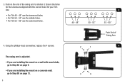
The swing arm is adjusted. • If you are installing the mount on a wall with wood studs, go to Step 5B on page 13. 8 3 40 - 48" 50 - 52" 55 - 60" Push End of the swing arm to Step 5A ...on page 9. • If you are aligned with the correct holes for the screws are installing the mount on the end of Swing Arm 2 1 4 3 4 Push on a concrete wall, go to shorten it. Ensure the holes for your TV's size: • For TVs 40 - 48" use the innermost holes...
The swing arm is adjusted. • If you are installing the mount on a wall with wood studs, go to Step 5B on page 13. 8 3 40 - 48" 50 - 52" 55 - 60" Push End of the swing arm to Step 5A ...on page 9. • If you are aligned with the correct holes for the screws are installing the mount on the end of Swing Arm 2 1 4 3 4 Push on a concrete wall, go to shorten it. Ensure the holes for your TV's size: • For TVs 40 - 48" use the innermost holes...
Quick Installation Guide
Page 11
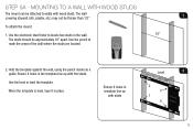
...in the template line up with the studs. Use the electronic stud finder to walls with wood studs. Ensure 4 holes in template line up with studs Level 2 2 3 1 4 9 To attach the mount: 1. Hold the template against the wall, using the pencil marks as a guide. When the template is level, ...approximately 16" apart. Use the level to mark the areas of the wall where the studs are located. 2. MOUNTING TO A WALL WITH WOOD STUDS The mount can be thicker than 1/2". Use the pencil to level the template. The wall 1 covering (drywall, lath, plaster, etc.) may not be attached ...
...in the template line up with the studs. Use the electronic stud finder to walls with wood studs. Ensure 4 holes in template line up with studs Level 2 2 3 1 4 9 To attach the mount: 1. Hold the template against the wall, using the pencil marks as a guide. When the template is level, ...approximately 16" apart. Use the level to mark the areas of the wall where the studs are located. 2. MOUNTING TO A WALL WITH WOOD STUDS The mount can be thicker than 1/2". Use the pencil to level the template. The wall 1 covering (drywall, lath, plaster, etc.) may not be attached ...

Quick Installation Guide
Page 13
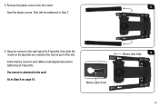
5. Remove the plastic covers from the mount. Save the plastic covers. Use the Thumb Hole 6. Mount, then slide 6 Narrow part of the slot. Use the thumb holes 5 to lift the covers away from the mount. They will be reattached in the narrow part of slot 11 Hang the mount on the wall using the 2 lag bolts, then slide the mount so the lag bolts are resting in Step 7.
5. Remove the plastic covers from the mount. Save the plastic covers. Use the Thumb Hole 6. Mount, then slide 6 Narrow part of the slot. Use the thumb holes 5 to lift the covers away from the mount. They will be reattached in the narrow part of slot 11 Hang the mount on the wall using the 2 lag bolts, then slide the mount so the lag bolts are resting in Step 7.
Quick Installation Guide
Page 14
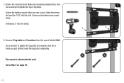
7. Ensure the mount is attached to Step 6 on page 16. 12 Drill about 2" into the 2 holes you just drilled. The mount is level. Using the power drill and the 7/32" drill bit, drill 2 holes in the bottom two mount holes. Go to the wall. Ensure the bottom mount holes are over a stud. Remove 2 lag bolts and 2 washers from the pouch labeled LAG. 8 Use a wrench to tighten the top 2 lag bolts. Make any necessary adjustments, then 7 use a wrench to tighten the lag bolts and washers into the studs. 1 2 8. Insert the lag bolts completely.
7. Ensure the mount is attached to Step 6 on page 16. 12 Drill about 2" into the 2 holes you just drilled. The mount is level. Using the power drill and the 7/32" drill bit, drill 2 holes in the bottom two mount holes. Go to the wall. Ensure the bottom mount holes are over a stud. Remove 2 lag bolts and 2 washers from the pouch labeled LAG. 8 Use a wrench to tighten the top 2 lag bolts. Make any necessary adjustments, then 7 use a wrench to tighten the lag bolts and washers into the studs. 1 2 8. Insert the lag bolts completely.

Quick Installation Guide
Page 15
Remove the template from the wall. 3 (choose one) 21 2 4 (choose one) 56 13 Hold the template against the wall, using the level to level the template. Using the power drill and the 1/2" drill bit, drill into 6 of the template holes as shown. Drill about 2 1/2" deep. STEP 5B - MOUNTING TO A CONCRETE WALL 1. Level 1 When the template is level, tape it in place. 2.
Remove the template from the wall. 3 (choose one) 21 2 4 (choose one) 56 13 Hold the template against the wall, using the level to level the template. Using the power drill and the 1/2" drill bit, drill into 6 of the template holes as shown. Drill about 2 1/2" deep. STEP 5B - MOUNTING TO A CONCRETE WALL 1. Level 1 When the template is level, tape it in place. 2.
Quick Installation Guide
Page 17
Verify that the mount is attached to Step 6 on the wall using the 6 lag bolts, then slide the mount so the lag bolts are resting in Step 7. 6. 5. Hang the mount on page 16. The mount is level. Remove the plastic covers from the mount. 5 Save the plastic covers. They will be reattached in the narrow part of slot Mount, then slide 6 15 Narrow part of the slot. Go to the wall. Make small adjustments before tightening all 6 lag bolts.
Verify that the mount is attached to Step 6 on the wall using the 6 lag bolts, then slide the mount so the lag bolts are resting in Step 7. 6. 5. Hang the mount on page 16. The mount is level. Remove the plastic covers from the mount. 5 Save the plastic covers. They will be reattached in the narrow part of slot Mount, then slide 6 15 Narrow part of the slot. Go to the wall. Make small adjustments before tightening all 6 lag bolts.


