
Quick Installation Guide
Page 1
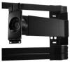
QUICK INSTALL GUIDE FULL ARTICULATING MOUNT UNIVERSAL FOR 40" - 60" TVS UP TO 120 LBS XMA1200 -
QUICK INSTALL GUIDE FULL ARTICULATING MOUNT UNIVERSAL FOR 40" - 60" TVS UP TO 120 LBS XMA1200 -

Quick Installation Guide
Page 2
... damage to vertical walls as instructed in this Quick Install Guide. This mounting system supports a maximum weight of 120 lbs and a maximum screen size of this mounting system. Keep all contents of 60". VIZIO is for damage or injury caused by incorrect mounting, assembly, or use only. IMPORTANT SAFETY INFORMATION Read the Important Safety...
... damage to vertical walls as instructed in this Quick Install Guide. This mounting system supports a maximum weight of 120 lbs and a maximum screen size of this mounting system. Keep all contents of 60". VIZIO is for damage or injury caused by incorrect mounting, assembly, or use only. IMPORTANT SAFETY INFORMATION Read the Important Safety...
Quick Installation Guide
Page 3
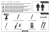
To make the installation easier and safer, have someone help you have all of the items listed on this page. Mounting a TV requires lifting. STEP 1 - Do not begin the installation, ensure you are unfamiliar with safe power tool use, consult a professional installer. TWO-PERSON JOB YOU ... Electronic Stud Finder Not Included Assorted Wrenches 1 BEFORE YOU BEGIN Before you begin the installation unless you . If you have all of the following items. Mounting a TV requires power tools. Always lift properly.
To make the installation easier and safer, have someone help you have all of the items listed on this page. Mounting a TV requires lifting. STEP 1 - Do not begin the installation, ensure you are unfamiliar with safe power tool use, consult a professional installer. TWO-PERSON JOB YOU ... Electronic Stud Finder Not Included Assorted Wrenches 1 BEFORE YOU BEGIN Before you begin the installation unless you . If you have all of the following items. Mounting a TV requires power tools. Always lift properly.

Quick Installation Guide
Page 4
REVIEW THE PACKAGE CONTENTS Before you begin, ensure all parts are missing or damaged, contact VIZIO Customer Service (877) 698-4946. If any parts are included and undamaged. x 2 Quick Install Guide & Wall-Mount Template x 1 x 2 (Attached to Mount) x 2 Sec X1 x 1 x 4 x 4 x 4 x 1 x 2 x 4 2 STEP 2 - To prevent loss, do not unpack the small parts until they are required.
REVIEW THE PACKAGE CONTENTS Before you begin, ensure all parts are missing or damaged, contact VIZIO Customer Service (877) 698-4946. If any parts are included and undamaged. x 2 Quick Install Guide & Wall-Mount Template x 1 x 2 (Attached to Mount) x 2 Sec X1 x 1 x 4 x 4 x 4 x 1 x 2 x 4 2 STEP 2 - To prevent loss, do not unpack the small parts until they are required.

Quick Installation Guide
Page 6
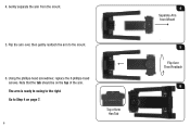
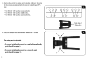
STEP 3 - The mount is assembled in Box - Arm Swings Left OR Arm Swings Right Mount in the box. Like a door, the mount can swing open to the left or to the left as it is ready to swing to the right. Ready to swing away from the wall like a door. CHOOSE THE DIRECTION OF SWING ARM The mount features an arm designed to Swing Left 4 Go to the left or to the right. If you want the arm to swing to Step 4 on page 7. Before you begin the installation, you must decide which direction you want the arm to swing-to the left , do nothing.
STEP 3 - The mount is assembled in Box - Arm Swings Left OR Arm Swings Right Mount in the box. Like a door, the mount can swing open to the left or to the left as it is ready to swing to the right. Ready to swing away from the wall like a door. CHOOSE THE DIRECTION OF SWING ARM The mount features an arm designed to Swing Left 4 Go to the left or to the right. If you want the arm to swing to Step 4 on page 7. Before you begin the installation, you must decide which direction you want the arm to swing-to the left , do nothing.

Quick Installation Guide
Page 7
If you want the mount to swing to the hinge. 43 2 1 3 5 There are close to the right: 1. Swing Arm Away 1 2 Hold Down 3. The correct screws are 2 screws inside the row of the arm. Hold down the mount as shown. 2 1 2. On the top of the arm, do not loosen the screws inside the arm and 2 screws on the floor. Using the screwdriver, remove the 2 philips-head screws as shown and swing the arm away from the arm. Lay the mount on the top of 9 holes. Using the screwdriver, remove the remaining 4 phillips-head screws from the mount.
If you want the mount to swing to the hinge. 43 2 1 3 5 There are close to the right: 1. Swing Arm Away 1 2 Hold Down 3. The correct screws are 2 screws inside the row of the arm. Hold down the mount as shown. 2 1 2. On the top of the arm, do not loosen the screws inside the arm and 2 screws on the floor. Using the screwdriver, remove the 2 philips-head screws as shown and swing the arm away from the arm. Lay the mount on the top of 9 holes. Using the screwdriver, remove the remaining 4 phillips-head screws from the mount.
Quick Installation Guide
Page 8
Note that the tab should be on page 7. 6 Top of the arm. 4. Go to Step 4 on the top of Arm Has Tab 4 Separate Arm from the mount. 5. Using the phillips-head screwdriver, replace the 6 phillips-head screws. The arm is ready to swing to the mount. 6. Flip the arm over, then gently reattach the arm to the right. Gently separate the arm from Mount 5 Flip Over Then Reattach 6
Note that the tab should be on page 7. 6 Top of the arm. 4. Go to Step 4 on the top of Arm Has Tab 4 Separate Arm from the mount. 5. Using the phillips-head screwdriver, replace the 6 phillips-head screws. The arm is ready to swing to the mount. 6. Flip the arm over, then gently reattach the arm to the right. Gently separate the arm from Mount 5 Flip Over Then Reattach 6
Quick Installation Guide
Page 9
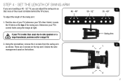
... arm so that more of the swing arm: 1. If your TV is hidden behind the TV screen. 40 - 48" To adjust the length of the mount is wider than usual due to side speakers or a large frame/bezel, use holes set for a larger TV. 2. Locate the 9 holes on the bottom. 50... - 52" 1 55 - 60" Swing Arm 2 2 1 3 4 7 There are mounting a 40 - 52" TV, you are 2 screws on the top and 2 inside the wire management canal on the top of your TV (reference your TV's correct...
... arm so that more of the swing arm: 1. If your TV is hidden behind the TV screen. 40 - 48" To adjust the length of the mount is wider than usual due to side speakers or a large frame/bezel, use holes set for a larger TV. 2. Locate the 9 holes on the bottom. 50... - 52" 1 55 - 60" Swing Arm 2 2 1 3 4 7 There are mounting a 40 - 52" TV, you are 2 screws on the top and 2 inside the wire management canal on the top of your TV (reference your TV's correct...
Quick Installation Guide
Page 10
The swing arm is adjusted. • If you are installing the mount on a wall with the correct holes for your TV's size: • For TVs 40 - 48" use the innermost holes. • For TVs 50 - 52" use ... holes. 4. Push on the end of Swing Arm 2 1 4 3 4 Using the phillips-head screwdriver, replace the 4 screws. Ensure the holes for the screws are installing the mount on page 13. 8 3 40 - 48" 50 - 52" 55 - 60" Push End of the swing arm to Step 5B on a concrete wall, go to Step 5A...
The swing arm is adjusted. • If you are installing the mount on a wall with the correct holes for your TV's size: • For TVs 40 - 48" use the innermost holes. • For TVs 50 - 52" use ... holes. 4. Push on the end of Swing Arm 2 1 4 3 4 Using the phillips-head screwdriver, replace the 4 screws. Ensure the holes for the screws are installing the mount on page 13. 8 3 40 - 48" 50 - 52" 55 - 60" Push End of the swing arm to Step 5B on a concrete wall, go to Step 5A...
Quick Installation Guide
Page 11
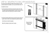
... the wall. 16" The studs should be approximately 16" apart. Use the level to mark the areas of the wall where the studs are located. 2. MOUNTING TO A WALL WITH WOOD STUDS The mount can be thicker than 1/2". To attach the...
... the wall. 16" The studs should be approximately 16" apart. Use the level to mark the areas of the wall where the studs are located. 2. MOUNTING TO A WALL WITH WOOD STUDS The mount can be thicker than 1/2". To attach the...

Quick Installation Guide
Page 13
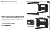
They will be reattached in the narrow part of slot 11 Hang the mount on the wall using the 2 lag bolts, then slide the mount so the lag bolts are resting in Step 7. 5. Use the thumb holes 5 to lift the covers away from the mount. Use the Thumb Hole 6. Save the plastic covers. Remove the plastic covers from the mount. Mount, then slide 6 Narrow part of the slot.
They will be reattached in the narrow part of slot 11 Hang the mount on the wall using the 2 lag bolts, then slide the mount so the lag bolts are resting in Step 7. 5. Use the thumb holes 5 to lift the covers away from the mount. Use the Thumb Hole 6. Save the plastic covers. Remove the plastic covers from the mount. Mount, then slide 6 Narrow part of the slot.
Quick Installation Guide
Page 14
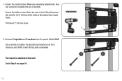
Drill about 2" into the 2 holes you just drilled. 7. Remove 2 lag bolts and 2 washers from the pouch labeled LAG. 8 Use a wrench to the wall. Ensure the mount is attached to tighten the lag bolts and washers into the studs. 1 2 8. Insert the lag bolts completely. Go to tighten the top 2 lag bolts. Using the power drill and the 7/32" drill bit, drill 2 holes in the bottom two mount holes. The mount is level. Make any necessary adjustments, then 7 use a wrench to Step 6 on page 16. 12 Ensure the bottom mount holes are over a stud.
Drill about 2" into the 2 holes you just drilled. 7. Remove 2 lag bolts and 2 washers from the pouch labeled LAG. 8 Use a wrench to the wall. Ensure the mount is attached to tighten the lag bolts and washers into the studs. 1 2 8. Insert the lag bolts completely. Go to tighten the top 2 lag bolts. Using the power drill and the 7/32" drill bit, drill 2 holes in the bottom two mount holes. The mount is level. Make any necessary adjustments, then 7 use a wrench to Step 6 on page 16. 12 Ensure the bottom mount holes are over a stud.

Quick Installation Guide
Page 15
Hold the template against the wall, using the level to level the template. Using the power drill and the 1/2" drill bit, drill into 6 of the template holes as shown. STEP 5B - Level 1 When the template is level, tape it in place. 2. MOUNTING TO A CONCRETE WALL 1. Remove the template from the wall. 3 (choose one) 21 2 4 (choose one) 56 13 Drill about 2 1/2" deep.
Hold the template against the wall, using the level to level the template. Using the power drill and the 1/2" drill bit, drill into 6 of the template holes as shown. STEP 5B - Level 1 When the template is level, tape it in place. 2. MOUNTING TO A CONCRETE WALL 1. Remove the template from the wall. 3 (choose one) 21 2 4 (choose one) 56 13 Drill about 2 1/2" deep.
Quick Installation Guide
Page 17
They will be reattached in the narrow part of slot Mount, then slide 6 15 The mount is level. Go to the wall. Hang the mount on page 16. Verify that the mount is attached to Step 6 on the wall using the 6 lag bolts, then slide the mount so the lag bolts are resting in Step 7. 6. Narrow part of the slot. Make small adjustments before tightening all 6 lag bolts. Remove the plastic covers from the mount. 5 Save the plastic covers. 5.
They will be reattached in the narrow part of slot Mount, then slide 6 15 The mount is level. Go to the wall. Hang the mount on page 16. Verify that the mount is attached to Step 6 on the wall using the 6 lag bolts, then slide the mount so the lag bolts are resting in Step 7. 6. Narrow part of the slot. Make small adjustments before tightening all 6 lag bolts. Remove the plastic covers from the mount. 5 Save the plastic covers. 5.

Quick Installation Guide
Page 18
... on the floor screen-down. Gently place the TV on the back of your TV's mounting holes. If you have a large screen (mounting holes are 200mm apart), place the brackets outward. If you do not have the User Guide, or the size is not listed, you may want ...to place a rug or blanket beneath the screen to try several sizes until you have to prevent scratches. You may have a small screen (mounting holes are 400-600mm apart), place the brackets inward. In your TV's User Guide, find one that matches your TV...
... on the floor screen-down. Gently place the TV on the back of your TV's mounting holes. If you have a large screen (mounting holes are 200mm apart), place the brackets outward. If you do not have the User Guide, or the size is not listed, you may want ...to place a rug or blanket beneath the screen to try several sizes until you have to prevent scratches. You may have a small screen (mounting holes are 400-600mm apart), place the brackets inward. In your TV's User Guide, find one that matches your TV...

Quick Installation Guide
Page 19
... TV has a curved back, or if your VIZIO TV mount includes screws of different lengths. Using the screwdriver, insert the screws, star washers, and 3 washers as shown. Because each TV is different, your TV has protruding components, place spacers between the brackets and the mounting holes. The spacers are in the pouch labeled...
... TV has a curved back, or if your VIZIO TV mount includes screws of different lengths. Using the screwdriver, insert the screws, star washers, and 3 washers as shown. Because each TV is different, your TV has protruding components, place spacers between the brackets and the mounting holes. The spacers are in the pouch labeled...

Quick Installation Guide
Page 21
Then, gently lower the bottom bracket so it on the horizontal bracket. Swing the arm away from the mount. 1 Swing Arm Away 2. First, hang the top bracket on Bracket 19 To prevent injury to yourself or damage to your TV, perform this step with the help of another person, lift the TV and hang it rests against the arm. 1 2 2 Tab on Arm Fits into the slot on the mount arm as shown. HANGING THE TV ON THE MOUNT This step requires lifting the TV. STEP 7 - With the help of another person. 1. The tab on the mount arm fits into Slot on the arm.
Then, gently lower the bottom bracket so it on the horizontal bracket. Swing the arm away from the mount. 1 Swing Arm Away 2. First, hang the top bracket on Bracket 19 To prevent injury to yourself or damage to your TV, perform this step with the help of another person, lift the TV and hang it rests against the arm. 1 2 2 Tab on Arm Fits into the slot on the mount arm as shown. HANGING THE TV ON THE MOUNT This step requires lifting the TV. STEP 7 - With the help of another person. 1. The tab on the mount arm fits into Slot on the arm.
Quick Installation Guide
Page 22
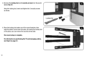
Remove the locking tool and 2 security screws from the pouch 3 labeled Sec X1. Using the locking tool, insert and tighten the 2 security screws as shown. By saving the locking tool in this place, you can remove the security screws later. Locking Tool 4. The mount setup is complete. 3. Place the locking tool inside one of the mount brackets, then 4 snap the plastic covers back into place. For information on positioning the TV and managing cables, see Step 8 on page 21. 20
Remove the locking tool and 2 security screws from the pouch 3 labeled Sec X1. Using the locking tool, insert and tighten the 2 security screws as shown. By saving the locking tool in this place, you can remove the security screws later. Locking Tool 4. The mount setup is complete. 3. Place the locking tool inside one of the mount brackets, then 4 snap the plastic covers back into place. For information on positioning the TV and managing cables, see Step 8 on page 21. 20
Quick Installation Guide
Page 23
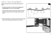
Before closing the zip-ties, lace each sticky mount and push the cables into the cavity running along the bottom of the mount arm. 1 3 4 2 21 To bundle and hide your TV's cables. 1. Remove the backing from the pouch labeled Sec X1. 1 2 Bundle the cables together and wrap them with zip-ties. STEP 6 - FINAL ADJUSTMENTS Using the included zip-ties, you can bundle and hide your TV's cables, take the 4 zip-ties and 4 sticky mounts from each one through a sticky mount as shown. 2.
Before closing the zip-ties, lace each sticky mount and push the cables into the cavity running along the bottom of the mount arm. 1 3 4 2 21 To bundle and hide your TV's cables. 1. Remove the backing from the pouch labeled Sec X1. 1 2 Bundle the cables together and wrap them with zip-ties. STEP 6 - FINAL ADJUSTMENTS Using the included zip-ties, you can bundle and hide your TV's cables, take the 4 zip-ties and 4 sticky mounts from each one through a sticky mount as shown. 2.

