
Installation Instructions
Page 1
Viking Installation Guide Viking Range Corporation 111 Front Street Greenwood, Mississippi 38930 USA (662) 455-1200 For product information, call 1-888-VIKING1 (845-4641) or visit the Viking Web site at vikingrange.com F20470G EN UL C UL (033111) Professional Hoods
Viking Installation Guide Viking Range Corporation 111 Front Street Greenwood, Mississippi 38930 USA (662) 455-1200 For product information, call 1-888-VIKING1 (845-4641) or visit the Viking Web site at vikingrange.com F20470G EN UL C UL (033111) Professional Hoods

Installation Instructions
Page 2
...; Damp environment approved models should be done by the National Fire Protection Association (NFPA), and the American Society for use with Viking hoods. READ AND SAVE THESE INSTRUCTIONS WARNING To reduce the risk of fire and to properly exhaust air, be locked, securely fasten ...the electricity to prevent back drafting. DEV900/DEV1200, VEV900/VEV1200, OR DEV1500, VEV1500 or integral blowers manufactured by the manufacturer. Viking hoods are equipped with warming shelf panel, install warming shelf panel first. Installation work and electrical wiring must always be protected from ...
...; Damp environment approved models should be done by the National Fire Protection Association (NFPA), and the American Society for use with Viking hoods. READ AND SAVE THESE INSTRUCTIONS WARNING To reduce the risk of fire and to properly exhaust air, be locked, securely fasten ...the electricity to prevent back drafting. DEV900/DEV1200, VEV900/VEV1200, OR DEV1500, VEV1500 or integral blowers manufactured by the manufacturer. Viking hoods are equipped with warming shelf panel, install warming shelf panel first. Installation work and electrical wiring must always be protected from ...

Installation Instructions
Page 3
...DO NOT USE WATER, including wet dishcloths or towels a violent steam explosion will result. 4. Other ventilators cannot be burned. 3. Wall Hoods w/Standard Ventilator Description 24" 30" 36" Duct cover width Duct cover depth Duct cover height Number of lights Number of filters Heat ... using recirculating kits. 460 CFM blower is being called. • You can fight the fire with this model. SMOTHER FLAMES with hood. 5 Wall Hoods w/Standard Ventilator 24", 30", & 36") (7.63"cm) A (Hood width) 24"W. 23-7/8" (60.6 cm) 30"W. 29-7/8" (76.2 cm) 36"W. 35-7/8" (91.1 cm) (301.25 " ...
...DO NOT USE WATER, including wet dishcloths or towels a violent steam explosion will result. 4. Other ventilators cannot be burned. 3. Wall Hoods w/Standard Ventilator Description 24" 30" 36" Duct cover width Duct cover depth Duct cover height Number of lights Number of filters Heat ... using recirculating kits. 460 CFM blower is being called. • You can fight the fire with this model. SMOTHER FLAMES with hood. 5 Wall Hoods w/Standard Ventilator 24", 30", & 36") (7.63"cm) A (Hood width) 24"W. 23-7/8" (60.6 cm) 30"W. 29-7/8" (76.2 cm) 36"W. 35-7/8" (91.1 cm) (301.25 " ...

Installation Instructions
Page 4
Clearance Dimensions (VWH 10"H. Wall Hoods w/Standard Ventilator) Top View 24"W. 30"W. 36"W. 24"W. 30"W. 36"W. 24"W. 30"W. 36"W. 24"W. 30"W. 36"W. duct location 1/2" (1.3 cm) 3-1/2" (8.9 cm) Electrical ...15/16" (37.9 cm) 17-15/16" (45.6 cm) D 5/8" (1.6 cm) 3-5/8" (9.2 cm) 6-5/8" (16.8 cm) B C 4" (10.2 cm) A 18" (4.6 cm) D 3-4" (1.9 cm) 3-7/8" (9.8 cm) 7" (17.8 cm) dia. Wall Hoods w/Standard Ventilator) (913.46"cm) ((6611356020""t..mmo40 accinmmx..)) 22((766418""..mt06moaccimmxn..))* * NOTE: When installing with a 24" high-shelf, the 27" (68.6 cm) max. dimensions must...
Clearance Dimensions (VWH 10"H. Wall Hoods w/Standard Ventilator) Top View 24"W. 30"W. 36"W. 24"W. 30"W. 36"W. 24"W. 30"W. 36"W. 24"W. 30"W. 36"W. duct location 1/2" (1.3 cm) 3-1/2" (8.9 cm) Electrical ...15/16" (37.9 cm) 17-15/16" (45.6 cm) D 5/8" (1.6 cm) 3-5/8" (9.2 cm) 6-5/8" (16.8 cm) B C 4" (10.2 cm) A 18" (4.6 cm) D 3-4" (1.9 cm) 3-7/8" (9.8 cm) 7" (17.8 cm) dia. Wall Hoods w/Standard Ventilator) (913.46"cm) ((6611356020""t..mmo40 accinmmx..)) 22((766418""..mt06moaccimmxn..))* * NOTE: When installing with a 24" high-shelf, the 27" (68.6 cm) max. dimensions must...

Installation Instructions
Page 5
Max duct run is recommended that the 1,500 CFM ventilator be hard wired with 2wire with gas char-grill. Wall Hoods) (913.46"cm) ((7611268672""t..mmo69 accinmmx..)) 33((796061""..t24mmoccaimmnx.)). 9 Wall Hoods Description 24" 30" 36" 42" 48" 54" 60" 66" Duct cover width 23-7/8" 29-7/8" (60.6 cm) (75.9 cm) ...) 42"W. 41-7/8" (106.4 cm) 48"W. 47-7/8" (121.6 cm) 54"W. 53-7/8" (136.8 cm) 60"W. 59-7/8" (152.1 cm) 66"W. 65-7/8" (167.3 cm) (15.62"cm) B (Hood depth) 24"D. 24" (61.0 cm) A 27"D. 27" (68.6 cm) (301.52"cm) (451.78"cm) B NOTE: Optional duct cover sold separately.
Max duct run is recommended that the 1,500 CFM ventilator be hard wired with 2wire with gas char-grill. Wall Hoods) (913.46"cm) ((7611268672""t..mmo69 accinmmx..)) 33((796061""..t24mmoccaimmnx.)). 9 Wall Hoods Description 24" 30" 36" 42" 48" 54" 60" 66" Duct cover width 23-7/8" 29-7/8" (60.6 cm) (75.9 cm) ...) 42"W. 41-7/8" (106.4 cm) 48"W. 47-7/8" (121.6 cm) 54"W. 53-7/8" (136.8 cm) 60"W. 59-7/8" (152.1 cm) 66"W. 65-7/8" (167.3 cm) (15.62"cm) B (Hood depth) 24"D. 24" (61.0 cm) A 27"D. 27" (68.6 cm) (301.52"cm) (451.78"cm) B NOTE: Optional duct cover sold separately.

Installation Instructions
Page 6
...) 41-7/8" (106.4 cm) 47-7/8" (121.6 cm) 53-7/8" (136.8 cm) 59-7/8" (152.1 cm) 65-7/8" (167.3 cm) B 300 or 600 CFM Interior Ventilator Installation for all Wall Hoods 24"W. 30"W. 36"W. 42"W. 48"W. 54"W. 60"W. 66"W. B 23-7/8" (60.6 cm) 29-7/8" (75.9 cm) 35-7/8" (91.1 cm) 41-7/8" (106.4 cm) 47-7/8" (121.6 cm) ...(106.4 cm) 47-7/8" (121.6 cm) 53-7/8" (136.8 cm) 59-7/8" (152.1 cm) 65-7/8" (167.3 cm) 1200 or 1500 CFM Exterior Ventilator Installation for all Wall Hoods 11 Wall Hoods) 24"W. 30"W. 36"W. 42"W. 48"W. 54"W. 60"W. 66"W. Top View A 11-15/16" (30.3 cm) 14-15/16" (37.9 cm) 17-15/16" ...
...) 41-7/8" (106.4 cm) 47-7/8" (121.6 cm) 53-7/8" (136.8 cm) 59-7/8" (152.1 cm) 65-7/8" (167.3 cm) B 300 or 600 CFM Interior Ventilator Installation for all Wall Hoods 24"W. 30"W. 36"W. 42"W. 48"W. 54"W. 60"W. 66"W. B 23-7/8" (60.6 cm) 29-7/8" (75.9 cm) 35-7/8" (91.1 cm) 41-7/8" (106.4 cm) 47-7/8" (121.6 cm) ...(106.4 cm) 47-7/8" (121.6 cm) 53-7/8" (136.8 cm) 59-7/8" (152.1 cm) 65-7/8" (167.3 cm) 1200 or 1500 CFM Exterior Ventilator Installation for all Wall Hoods 11 Wall Hoods) 24"W. 30"W. 36"W. 42"W. 48"W. 54"W. 60"W. 66"W. Top View A 11-15/16" (30.3 cm) 14-15/16" (37.9 cm) 17-15/16" ...

Installation Instructions
Page 7
...Max duct run is recommended that the 1,500 CFM ventilator be used for hoods includes recommended ventilator kit rating; Dimensions & Specifications (VWH 18"H. Max duct run is 50 ft. ** It is 75 ft. Viking also recommends using a backsplash. 13 Provided on "T" Series only. (15....62"cm) A (Hood width) 36"W. 35-7/8" (91.1 cm) A 48"W. 47-7/8" (121.6 cm) 60"W. 59-7/8" (152.1 cm) (...
...Max duct run is recommended that the 1,500 CFM ventilator be used for hoods includes recommended ventilator kit rating; Dimensions & Specifications (VWH 18"H. Max duct run is 50 ft. ** It is 75 ft. Viking also recommends using a backsplash. 13 Provided on "T" Series only. (15....62"cm) A (Hood width) 36"W. 35-7/8" (91.1 cm) A 48"W. 47-7/8" (121.6 cm) 60"W. 59-7/8" (152.1 cm) (...

Installation Instructions
Page 8
... be used when installed over range/rangetop with all 18"H. or exterior-power ventilator kit must be used with ground. Dimensions & Specifications (VCWH Chimney Wall Hoods 30", 36", 42", 48", 54", 60", & 66") A A (Duct width) 30"W. 12" (30.5 cm) 36"W. 12" (30.5 cm) 42"W. 12" (30.5 cm) 48"W. 18" (...45.7 cm) 54"W. 18" (45.7 cm) 60"W. 24" (61.0 cm) 66"W. 24" (61.0 cm) B (Hood width) 30"W. 29-7/8" (76.2 cm) (15.62"cm) 36"W. 35-7/8" (91.1 cm) 42"W. 41-7/8" (106.4 cm) 48"W. 47-7/8" (121.6 cm) 54"W. 53-7/8" (136.8 cm) 60...
... be used when installed over range/rangetop with all 18"H. or exterior-power ventilator kit must be used with ground. Dimensions & Specifications (VCWH Chimney Wall Hoods 30", 36", 42", 48", 54", 60", & 66") A A (Duct width) 30"W. 12" (30.5 cm) 36"W. 12" (30.5 cm) 42"W. 12" (30.5 cm) 48"W. 18" (...45.7 cm) 54"W. 18" (45.7 cm) 60"W. 24" (61.0 cm) 66"W. 24" (61.0 cm) B (Hood width) 30"W. 29-7/8" (76.2 cm) (15.62"cm) 36"W. 35-7/8" (91.1 cm) 42"W. 41-7/8" (106.4 cm) 48"W. 47-7/8" (121.6 cm) 54"W. 53-7/8" (136.8 cm) 60...

Installation Instructions
Page 9
... 29-15/16" (76.0 cm) 32-15/16" (83.7 cm) 6" (15.2 cm) 1-1/2" (3.8 cm) 48"W. 54"W. 60"W. 66"W. Interior Ventilator Dimensions (VCWH Chimney Wall Hoods) Top View 12" (30.5 cm) 1-1/2" (3.8 cm) A 120V power supply 30"W. 36"W. 42"W. 30"W. 36"W. 42"W. A 14-15/16" (37.9 cm) 17-15/16....0 cm) 900, 1200 or 1500 CFM Exterior or In-Line Ventilator Installation for 48", 54", 60", & 66" models 16 Exterior Ventilator Dimensions (VCWH Chimney Wall Hoods) Top View 12" (30.5 cm) 1-1/2" (3.8 cm) A 120V power supply 30"W. 36"W. 42"W. 30"W. 36"W. 42"W. duct location B C 18" (45.7 cm) 18...
... 29-15/16" (76.0 cm) 32-15/16" (83.7 cm) 6" (15.2 cm) 1-1/2" (3.8 cm) 48"W. 54"W. 60"W. 66"W. Interior Ventilator Dimensions (VCWH Chimney Wall Hoods) Top View 12" (30.5 cm) 1-1/2" (3.8 cm) A 120V power supply 30"W. 36"W. 42"W. 30"W. 36"W. 42"W. A 14-15/16" (37.9 cm) 17-15/16....0 cm) 900, 1200 or 1500 CFM Exterior or In-Line Ventilator Installation for 48", 54", 60", & 66" models 16 Exterior Ventilator Dimensions (VCWH Chimney Wall Hoods) Top View 12" (30.5 cm) 1-1/2" (3.8 cm) A 120V power supply 30"W. 36"W. 42"W. 30"W. 36"W. 42"W. duct location B C 18" (45.7 cm) 18...

Installation Instructions
Page 10
...Exterior ventilator kits In-line ventilator kits Interior duct size Exterior duct size Interior-Maximum amps Exterior-Maximum amps In-Line-Maximum amps VIH Island Hoods 36" 42" 54" 35-7/8" (91.1 cm) 41-7/8" (106.4 cm) 53-7/8" (136.8 cm) 12" (30.5 cm)...7.3 66" 65-7/8" (167.3 cm) 8 8 VINV1200* DEV1200*/1500** DIL1200 10" (25.4 cm) 9.3 6.3/7.1 8.1 * A 1,200 CFM interior- hoods. 18 Clearance Dimensions (VIH Island Hoods) (913.46"cm) ((7611268672""t..mmo69 accinmmx..)) 33((796061""..t24mmoccaimmnx.)). 19 Max duct run is recommended that the 1,500 CFM ventilator be purchased for...
...Exterior ventilator kits In-line ventilator kits Interior duct size Exterior duct size Interior-Maximum amps Exterior-Maximum amps In-Line-Maximum amps VIH Island Hoods 36" 42" 54" 35-7/8" (91.1 cm) 41-7/8" (106.4 cm) 53-7/8" (136.8 cm) 12" (30.5 cm)...7.3 66" 65-7/8" (167.3 cm) 8 8 VINV1200* DEV1200*/1500** DIL1200 10" (25.4 cm) 9.3 6.3/7.1 8.1 * A 1,200 CFM interior- hoods. 18 Clearance Dimensions (VIH Island Hoods) (913.46"cm) ((7611268672""t..mmo69 accinmmx..)) 33((796061""..t24mmoccaimmnx.)). 19 Max duct run is recommended that the 1,500 CFM ventilator be purchased for...

Installation Instructions
Page 11
... 8-3/8" 120 (21.3 cm) V 10" (25.4 cm) dia. duct location 9-1/8" (23.2 cm) 120 V 9-5/8" (24.4 cm) B 600 CFM Interior Ventilator Installation for all Island Hoods Top View A 36"W. 42"W. 54"W. 66"W. 36"W. 42"W. 54"W. 66"W. A A 17-15/16" (45.6 cm) 20-15/16" (18.2 cm) 26-15/16" (... 8-1/4" (20.9 cm) 6-7/16" (16.4 cm) 120 V 3" (7.62 cm) 2-1/2" (6.35 cm) B 900 or 1200 CFM Exterior or In-Line Ventilator Installation for all Island Hoods Top View 36"W. 42"W. 54"W. 66"W. 36"W. 42"W. 54"W. 66"W. duct location A 8-3/16" (20.7 cm) 6-5/8" (6.35 cm) 120 3" (7.62 cm) V 2-1/2" (6.35...
... 8-3/8" 120 (21.3 cm) V 10" (25.4 cm) dia. duct location 9-1/8" (23.2 cm) 120 V 9-5/8" (24.4 cm) B 600 CFM Interior Ventilator Installation for all Island Hoods Top View A 36"W. 42"W. 54"W. 66"W. 36"W. 42"W. 54"W. 66"W. A A 17-15/16" (45.6 cm) 20-15/16" (18.2 cm) 26-15/16" (... 8-1/4" (20.9 cm) 6-7/16" (16.4 cm) 120 V 3" (7.62 cm) 2-1/2" (6.35 cm) B 900 or 1200 CFM Exterior or In-Line Ventilator Installation for all Island Hoods Top View 36"W. 42"W. 54"W. 66"W. 36"W. 42"W. 54"W. 66"W. duct location A 8-3/16" (20.7 cm) 6-5/8" (6.35 cm) 120 3" (7.62 cm) V 2-1/2" (6.35...

Installation Instructions
Page 12
...cm) 24" (70.0 cm) B (Duct height) 36"W. 42"W. 54"W. 66"W. 12" (30.5 cm) or 24" (61.0 cm) or 36" (91.4 cm) (15.62"cm) C (Hood width) 36"W. 35-7/8" (91.1 cm) C 42"W. 41-7/8" (106.4 cm) 54"W. 53-7/8" (136.8 cm) 66"W. 65-7/8" (167.3 cm) (763.20"cm) B (451.78"cm) NOTE...: Optional duct cover sold separately. VCIH Chimney Island Hoods Description Duct cover width Duct cover depth Duct cover height Number of lights Number of filters Heat lamps Interior ventilator kits Exterior ventilator kits In...
...cm) 24" (70.0 cm) B (Duct height) 36"W. 42"W. 54"W. 66"W. 12" (30.5 cm) or 24" (61.0 cm) or 36" (91.4 cm) (15.62"cm) C (Hood width) 36"W. 35-7/8" (91.1 cm) C 42"W. 41-7/8" (106.4 cm) 54"W. 53-7/8" (136.8 cm) 66"W. 65-7/8" (167.3 cm) (763.20"cm) B (451.78"cm) NOTE...: Optional duct cover sold separately. VCIH Chimney Island Hoods Description Duct cover width Duct cover depth Duct cover height Number of lights Number of filters Heat lamps Interior ventilator kits Exterior ventilator kits In...

Installation Instructions
Page 13
... (17.8 cm) dia. duct location B 120 V power supply 1-1/8" (2.9 cm) 1200 CFM Interior Ventilator Installation for all Chimney Island Hoods 24 Exterior Ventilator Dimensions (VCIH Chimney Island Hoods) 36"W. 42"W. 36"W. 42"W. duct location B 120 V power supply 1-1/8" (2.9 cm) 900, 1200 or 1500 CFM Exterior or ...In-Line Ventilator Installation for all Chimney Island Hoods 25 Top View 12" (30.5 cm) A 17-15/16" (45.6 cm) 20-15/16" (53.2 cm) B 35-7/8" (91.1 cm) 41-7/8" (...
... (17.8 cm) dia. duct location B 120 V power supply 1-1/8" (2.9 cm) 1200 CFM Interior Ventilator Installation for all Chimney Island Hoods 24 Exterior Ventilator Dimensions (VCIH Chimney Island Hoods) 36"W. 42"W. 36"W. 42"W. duct location B 120 V power supply 1-1/8" (2.9 cm) 900, 1200 or 1500 CFM Exterior or ...In-Line Ventilator Installation for all Chimney Island Hoods 25 Top View 12" (30.5 cm) A 17-15/16" (45.6 cm) 20-15/16" (53.2 cm) B 35-7/8" (91.1 cm) 41-7/8" (...

Installation Instructions
Page 14
... 30" W. 36" W. 42" W. 48" W. 54" W. 60" W. 66" W. or exterior-power ventilator kit must be used with the screws provided. Wall Hoods A (Hood Width) 27-7/16" (69.7 cm) 33-7/16" (84.9 cm) 39-7/16" (100.2 cm) 45-7/16" (115.4 cm) 51-7/16" (130.7 cm)...results, center the unit over range/rangetop with ground. NOTE: Maximum amp rating for installation with all 18"H. hoods. 26 Installing Hood Canopy (Custom Hood Canopy Cutouts) Custom Hood Canopy A B 1) Position ventilator system inside of the custom hood canopy and center it front to rear of filters 2 2 2 3 3 4 4 Heat lamps 1 1...
... 30" W. 36" W. 42" W. 48" W. 54" W. 60" W. 66" W. or exterior-power ventilator kit must be used with the screws provided. Wall Hoods A (Hood Width) 27-7/16" (69.7 cm) 33-7/16" (84.9 cm) 39-7/16" (100.2 cm) 45-7/16" (115.4 cm) 51-7/16" (130.7 cm)...results, center the unit over range/rangetop with ground. NOTE: Maximum amp rating for installation with all 18"H. hoods. 26 Installing Hood Canopy (Custom Hood Canopy Cutouts) Custom Hood Canopy A B 1) Position ventilator system inside of the custom hood canopy and center it front to rear of filters 2 2 2 3 3 4 4 Heat lamps 1 1...

Installation Instructions
Page 15
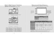
... Ventilator Installation 30", 36", 42" W. C 28-1/4" (71.8 cm) 34-1/4" (87.0 cm) 40-1/4" (102.2 cm) 30" W. 36" W. 42" W. Clearance Dimensions (VBCV Wall Custom Ventilator System) (Custom Hood) (913.46"cm) ((7611268672""t..mmo69 accinmmx..)) 33((796061""..t24mmoccaimmnx.)). 28 Built-In Wall Custom Ventilator System Dimensions (VBCV Models) 1-1/2" (3.81 cm) 1" (2.54 cm) 5/8" (1.6 cm) 21...
... Ventilator Installation 30", 36", 42" W. C 28-1/4" (71.8 cm) 34-1/4" (87.0 cm) 40-1/4" (102.2 cm) 30" W. 36" W. 42" W. Clearance Dimensions (VBCV Wall Custom Ventilator System) (Custom Hood) (913.46"cm) ((7611268672""t..mmo69 accinmmx..)) 33((796061""..t24mmoccaimmnx.)). 28 Built-In Wall Custom Ventilator System Dimensions (VBCV Models) 1-1/2" (3.81 cm) 1" (2.54 cm) 5/8" (1.6 cm) 21...
Installation Instructions
Page 16
...cm) 10" (25.4 cm) dia. Max duct run is 50 ft. ** It is 75 ft. All products must be purchased for hoods includes recommended ventilator kit rating; right to back; Max duct run is recommended that the 1,500 CFM ventilator be hard wired with 2wire with....0 cm) 27-9/16" (70.0 cm) 27-9/16" (70.0 cm) VICV Island Custom Ventilator System Description 36" 42" 54" Number of lights 4 4 6 Number of the custom hood canopy is flush with gas char-grill. duct location 18-1/2" (50.0 cm) D 9-3/8" (23.8 cm) 120 V 9-1/4" 9-1/2" (23.5 cm) (24.4 cm) 8-3/8" (21.3 cm) 5/8" (1.6 ...
...cm) 10" (25.4 cm) dia. Max duct run is 50 ft. ** It is 75 ft. All products must be purchased for hoods includes recommended ventilator kit rating; right to back; Max duct run is recommended that the 1,500 CFM ventilator be hard wired with 2wire with....0 cm) 27-9/16" (70.0 cm) 27-9/16" (70.0 cm) VICV Island Custom Ventilator System Description 36" 42" 54" Number of lights 4 4 6 Number of the custom hood canopy is flush with gas char-grill. duct location 18-1/2" (50.0 cm) D 9-3/8" (23.8 cm) 120 V 9-1/4" 9-1/2" (23.5 cm) (24.4 cm) 8-3/8" (21.3 cm) 5/8" (1.6 ...

Installation Instructions
Page 17
Built-In Ventilator System 3) OPTIONAL Rear mounting holes fasten ventilator system to bottom of custom hood canopy. 32 Clearance Dimensions (VICV Island Custom Ventilator System) (913.46"cm) (Custom Hood) ((7611268672""t..mmo69 accinmmx..)) 33((796061""..t24mmoccaimmnx.)). 33 Installing Hood Canopy (Custom Hood Canopy Cutouts) Custom Hood Canopy A B 1) Position ventilator system inside of the custom hood canopy and center it front to back and left to right. 2) Bottom mounting holes fasten ventilator system to rear of custom hood canopy with the screws provided.
Built-In Ventilator System 3) OPTIONAL Rear mounting holes fasten ventilator system to bottom of custom hood canopy. 32 Clearance Dimensions (VICV Island Custom Ventilator System) (913.46"cm) (Custom Hood) ((7611268672""t..mmo69 accinmmx..)) 33((796061""..t24mmoccaimmnx.)). 33 Installing Hood Canopy (Custom Hood Canopy Cutouts) Custom Hood Canopy A B 1) Position ventilator system inside of the custom hood canopy and center it front to back and left to right. 2) Bottom mounting holes fasten ventilator system to rear of custom hood canopy with the screws provided.

Installation Instructions
Page 19
...transition to local codes. Refer to damper. amp rating for the most common installations are shown. Recommended hood locations for hoods includes recommended ventilator kit rating; Hood NOTE: Wall exhaust must be greatly overstated. • Straight runs and gradual turns are using wiring ...ducting is extremely important to ensure maximum performance from any . • Max. for unrestricted movement, adjust if necessary. 3 Flip hood over transition and tape around joint. 37 it creates back pressure/air turbulence and greatly reduces performance. • Proper performance is...
...transition to local codes. Refer to damper. amp rating for the most common installations are shown. Recommended hood locations for hoods includes recommended ventilator kit rating; Hood NOTE: Wall exhaust must be greatly overstated. • Straight runs and gradual turns are using wiring ...ducting is extremely important to ensure maximum performance from any . • Max. for unrestricted movement, adjust if necessary. 3 Flip hood over transition and tape around joint. 37 it creates back pressure/air turbulence and greatly reduces performance. • Proper performance is...

Installation Instructions
Page 20
...unit. 39 6 5/16" nut driver CAUTION: Secure vent hood to be properly installed for wiring to wall using screws provided. Wall Hoods w/Recirculating Kit) 1 2 Remove damper and discard with transition. Place vent hood upside down . Installation (VWH 10"H. Make connection to white,...if necessary. 8 1 1 2 Connect black to black, white to breaker box. 10 1 3 2 Slide filter front over front lip. Wall Hoods w/Standard Ventilator) 1 2 2 Measure distance from inside canopy using screws provided, make sure top mounting screws are secured into soffit or cabinet framing....
...unit. 39 6 5/16" nut driver CAUTION: Secure vent hood to be properly installed for wiring to wall using screws provided. Wall Hoods w/Recirculating Kit) 1 2 Remove damper and discard with transition. Place vent hood upside down . Installation (VWH 10"H. Make connection to white,...if necessary. 8 1 1 2 Connect black to black, white to breaker box. 10 1 3 2 Slide filter front over front lip. Wall Hoods w/Standard Ventilator) 1 2 2 Measure distance from inside canopy using screws provided, make sure top mounting screws are secured into soffit or cabinet framing....

Installation Instructions
Page 21
Make connection to breaker box. 11 1 Assemble brackets to the service panel. 6 7 1 5/16" nut driver 2 Flip hood over front lip. Attach with screws and lock washers provided. 5 Remove electrical box cover. When the service disconnecting means cannot be correct when wiring ... electrical wiring through the top of fire, electric shock, or injury to white, and the green/bare wire under the green screw. CAUTION: Secure vent hood. Use additional mounting screws and wall anchors, if necessary. 40 8 BARE OR GREEN WHITE WHITE GREEN BLACK BLACK 9 1 1 2 Connect black to black, white ...
Make connection to breaker box. 11 1 Assemble brackets to the service panel. 6 7 1 5/16" nut driver 2 Flip hood over front lip. Attach with screws and lock washers provided. 5 Remove electrical box cover. When the service disconnecting means cannot be correct when wiring ... electrical wiring through the top of fire, electric shock, or injury to white, and the green/bare wire under the green screw. CAUTION: Secure vent hood. Use additional mounting screws and wall anchors, if necessary. 40 8 BARE OR GREEN WHITE WHITE GREEN BLACK BLACK 9 1 1 2 Connect black to black, white ...


