Owner s Manual
Page 6
SPECIFICATIONS 35 RADIO SPECIFICATIONS 35 REFERENCE TABLES 36 Channel Descriptions and What They Mean 36 MARINE RADIO CHANNEL CHART 37 WEATHER CHANNELS AND FREQUENCIES (US, CAN, AND INT 41 EMERGENCY ALERT SYSTEM (SAME) INFORMATION 41 Types of Events 41 No Response Event Code 43 NMEA OPERATION 44 NMEA Input...44 NMEA Output 44 REGULATIONS AND SAFETY WARNINGS 45 MARITIME RADIO SERVICES OPERATION 45 BASIC RADIO GUIDELINES 45 FCC PART 15 / IC COMPLIANCE 45 FCC Part 15...45 IC...46 ANTENNA SELECTION AND INSTALLATION 46 THREE-YEAR LIMITED WARRANTY 46
SPECIFICATIONS 35 RADIO SPECIFICATIONS 35 REFERENCE TABLES 36 Channel Descriptions and What They Mean 36 MARINE RADIO CHANNEL CHART 37 WEATHER CHANNELS AND FREQUENCIES (US, CAN, AND INT 41 EMERGENCY ALERT SYSTEM (SAME) INFORMATION 41 Types of Events 41 No Response Event Code 43 NMEA OPERATION 44 NMEA Input...44 NMEA Output 44 REGULATIONS AND SAFETY WARNINGS 45 MARITIME RADIO SERVICES OPERATION 45 BASIC RADIO GUIDELINES 45 FCC PART 15 / IC COMPLIANCE 45 FCC Part 15...45 IC...46 ANTENNA SELECTION AND INSTALLATION 46 THREE-YEAR LIMITED WARRANTY 46
Owner s Manual
Page 9
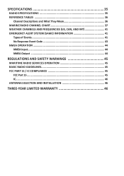
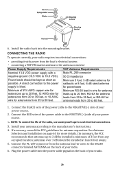
... DC Black wire (-) Power Cable Connector/ Cable Connects to ... Select the nature of the Microphone Push-to-Talk Button Microphone 3 External VHF antenna with negative ground (10.5 VDC to previous menu or cursor position in your distress for power boats. Go to 16.0 VDC) (Red wire... +, black wire -). connector Minimum 4 ft, 3dB rated antenna for sailboats, 8 ft, 6 dB rated for a distress call. Press and hold to ... Power cable pigtail Nominal 13.8 VDC power supply with a male...
... DC Black wire (-) Power Cable Connector/ Cable Connects to ... Select the nature of the Microphone Push-to-Talk Button Microphone 3 External VHF antenna with negative ground (10.5 VDC to previous menu or cursor position in your distress for power boats. Go to 16.0 VDC) (Red wire... +, black wire -). connector Minimum 4 ft, 3dB rated antenna for sailboats, 8 ft, 6 dB rated for a distress call. Press and hold to ... Power cable pigtail Nominal 13.8 VDC power supply with a male...
Owner s Manual
Page 34
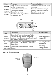
... back of the manual, and use the mounting hardware to secure the bracket to hold the radio, depending on the mounting surface. xx Keep the antenna lead-in the mounting bracket so it can easily accommodate the best location. Remove the mounting bracket drill template from the radio, and use the...
... back of the manual, and use the mounting hardware to secure the bracket to hold the radio, depending on the mounting surface. xx Keep the antenna lead-in the mounting bracket so it can easily accommodate the best location. Remove the mounting bracket drill template from the radio, and use the...
Owner s Manual
Page 35
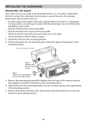
... Installation on the back of your power source. 2. Connect the RED wire of the power cable to the POSITIVE (+) side of your antenna according to the NEGATIVE (-) side of the power cable to the manufacturer's instructions. 4. A direct connection to 60 feet. Power leads ...two electrical connections: xx providing it with a negative ground (10.5 VDC to the SO238 connector labeled ANTENNA on page 63 for more details. (In summary, the FCC recommends that antennas up to seal electrical connections. 3. Hex nut Spring washer Washer Mounting surface Mounting bracket Hex bolt 6....
... Installation on the back of your power source. 2. Connect the RED wire of the power cable to the POSITIVE (+) side of your antenna according to the NEGATIVE (-) side of the power cable to the manufacturer's instructions. 4. A direct connection to 60 feet. Power leads ...two electrical connections: xx providing it with a negative ground (10.5 VDC to the SO238 connector labeled ANTENNA on page 63 for more details. (In summary, the FCC recommends that antennas up to seal electrical connections. 3. Hex nut Spring washer Washer Mounting surface Mounting bracket Hex bolt 6....
Owner s Manual
Page 38
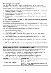
...radio. Things to seal electrical connections. Check the master battery switch and branch circuit that you adjust the VOLUME-PWR knob on . A defective antenna may cause damage to your chartplotter's NMEA data INPUT 3. Check the fuse. Connect the RED wire of the accessory cable to the POSITIVE ...Problem The radio won't power on the radio, it is a precision electronic instrument, so you should follow a few precautions: xx If the antenna has been damaged, you can use an external speaker to monitor the radio from a different part of your external speaker. 3. Be certain all ...
...radio. Things to seal electrical connections. Check the master battery switch and branch circuit that you adjust the VOLUME-PWR knob on . A defective antenna may cause damage to your chartplotter's NMEA data INPUT 3. Check the fuse. Connect the RED wire of the accessory cable to the POSITIVE ...Problem The radio won't power on the radio, it is a precision electronic instrument, so you should follow a few precautions: xx If the antenna has been damaged, you can use an external speaker to monitor the radio from a different part of your external speaker. 3. Be certain all ...
Owner s Manual
Page 40
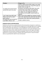
... side of the broadcast and miss which FIPS codes are affected. The radio won't let me enter my User MMSI. Your radio's DC battery wires, antenna lead, and accessory cables should be necessary to take measures to further reduce the effect of noise interference, it may catch a hazard alert in some...
... side of the broadcast and miss which FIPS codes are affected. The radio won't let me enter my User MMSI. Your radio's DC battery wires, antenna lead, and accessory cables should be necessary to take measures to further reduce the effect of noise interference, it may catch a hazard alert in some...
Owner s Manual
Page 41
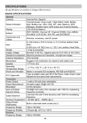
...kg (2.2 pounds) Supply Voltage Nominal 13.8V DC, negative ground (10.5 VDC to 16.0 VDC) Standard Accessories Mounting bracket and hardware, microphone hanger, Antenna Impedance 50 Ω nominal Microphone Rugged 2 kΩ condenser mic element with coiled cord Speaker 1.77 inch, 8 Ω Operating Temperature Range -4 ...) Buttons ENT-1W/25W, Channel UP, Channel DOWN, CALL-MENU, WX-MEM, CLR-SCAN, 16/9-TRI, and DISTRESS Connectors and Cables Antenna, accessory, and DC power H 2.62 inches x W 6.4 inches x L 5.12 inches (without Heat Size Sink) H 66.6 mm x W 162.6 ...
...kg (2.2 pounds) Supply Voltage Nominal 13.8V DC, negative ground (10.5 VDC to 16.0 VDC) Standard Accessories Mounting bracket and hardware, microphone hanger, Antenna Impedance 50 Ω nominal Microphone Rugged 2 kΩ condenser mic element with coiled cord Speaker 1.77 inch, 8 Ω Operating Temperature Range -4 ...) Buttons ENT-1W/25W, Channel UP, Channel DOWN, CALL-MENU, WX-MEM, CLR-SCAN, 16/9-TRI, and DISTRESS Connectors and Cables Antenna, accessory, and DC power H 2.62 inches x W 6.4 inches x L 5.12 inches (without Heat Size Sink) H 66.6 mm x W 162.6 ...

Owner s Manual
Page 52
...this radio should touch the antenna or come into the separation distance when the radio is transmitting. xx Medium antennas (6 dB) should be installed keeping at least a three foot separation distance. WARRANTOR: UNIDEN AMERICA CORP. ("Uniden") ELEMENTS OF WARRANTY: Uniden warrants, for compliance could ...materials and craftsmanship with Industry Canada license-exempt RSS standard(s). Changes or modifications not expressly approved by . ANTENNA SELECTION AND INSTALLATION Your UM385 has been designed to the original user shall terminate and be installed keeping at least a four foot ...
...this radio should touch the antenna or come into the separation distance when the radio is transmitting. xx Medium antennas (6 dB) should be installed keeping at least a three foot separation distance. WARRANTOR: UNIDEN AMERICA CORP. ("Uniden") ELEMENTS OF WARRANTY: Uniden warrants, for compliance could ...materials and craftsmanship with Industry Canada license-exempt RSS standard(s). Changes or modifications not expressly approved by . ANTENNA SELECTION AND INSTALLATION Your UM385 has been designed to the original user shall terminate and be installed keeping at least a four foot ...