Owner's Manual for SU80K UPS 932793
Page 4
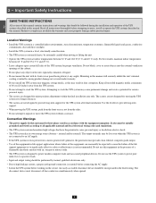
...8226; Install the UPS system in a level, structurally sound location. 4 • The UPS system is extremely heavy; Connection Warnings 9 • The power supply for this unit must be extremely careful when moving the UPS system, push from the front or rear, not from electric shock. 10 • The...only. • Due to high leakage current, a proper earth ground connection is not connected to an AC supply. • If the UPS system receives power from a motor-powered AC generator, the generator must disconnect all sides of the life 11 support equipment or to comply may cause ...
...8226; Install the UPS system in a level, structurally sound location. 4 • The UPS system is extremely heavy; Connection Warnings 9 • The power supply for this unit must be extremely careful when moving the UPS system, push from the front or rear, not from electric shock. 10 • The...only. • Due to high leakage current, a proper earth ground connection is not connected to an AC supply. • If the UPS system receives power from a motor-powered AC generator, the generator must disconnect all sides of the life 11 support equipment or to comply may cause ...
Owner's Manual for SU80K UPS 932793
Page 6
...supply is present and within standard operating parameters. 5 •B "BATTERY" LED: This amber light illuminates when the UPS system is in several screens. An audible alarm will also sound. • C 6 • D "BYPASS" LED: This amber light illuminates when the UPS system is in battery backup mode, discharging the batteries to provide power...conditions and diagnostic data. Failure to recharge the batteries may cause irreversible battery damage. •K "EPO" (Emergency Power Off) Button: Press this button for data entry in online (normal) mode. At a minimum, the batteries ...
...supply is present and within standard operating parameters. 5 •B "BATTERY" LED: This amber light illuminates when the UPS system is in several screens. An audible alarm will also sound. • C 6 • D "BYPASS" LED: This amber light illuminates when the UPS system is in battery backup mode, discharging the batteries to provide power...conditions and diagnostic data. Failure to recharge the batteries may cause irreversible battery damage. •K "EPO" (Emergency Power Off) Button: Press this button for data entry in online (normal) mode. At a minimum, the batteries ...
Owner's Manual for SU80K UPS 932793
Page 17
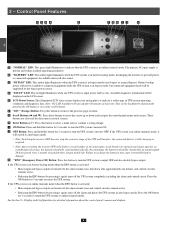
... the UPS system automatically switches to auto bypass mode to continue supplying power to online (normal) mode automatically. If the UPS system detects a bypass power source that connected equipment receives ideal power at all problems are eliminated, the UPS system switches back to...Single UPS) In online (normal) mode, the UPS system's rectifier converts incoming Q3 AC utility power to precision-regulated, pure sine wave AC power that charges the batteries and supplies the inverter. After confirming that supports the operation of connected equipment. The UPS system's batteries (...
... the UPS system automatically switches to auto bypass mode to continue supplying power to online (normal) mode automatically. If the UPS system detects a bypass power source that connected equipment receives ideal power at all problems are eliminated, the UPS system switches back to...Single UPS) In online (normal) mode, the UPS system's rectifier converts incoming Q3 AC utility power to precision-regulated, pure sine wave AC power that charges the batteries and supplies the inverter. After confirming that supports the operation of connected equipment. The UPS system's batteries (...

Owner's Manual for SU80K UPS 932793
Page 21
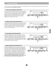
... Q4 4 ON I 5 Back Panel A 6 7 8-4 Battery Start-Up Procedure (Single UPS) 8 Note: The battery must be supplied by OFF the bypass power source. If the AC input power source is normal, the UPS system is ready for start-up. 3 Front Panel •5 Press the ON button A for this operation...1 •2 Confirm that the manual bypass circuit breaker switch Q3 is off. The "BATTERY" LED will activate and use stored DC battery power to supply AC power to online (normal) mode. 8 - Main Input •4 Switch on the bypass input circuit breaker switch Q2 then output circuit breaker switch...
... Q4 4 ON I 5 Back Panel A 6 7 8-4 Battery Start-Up Procedure (Single UPS) 8 Note: The battery must be supplied by OFF the bypass power source. If the AC input power source is normal, the UPS system is ready for start-up. 3 Front Panel •5 Press the ON button A for this operation...1 •2 Confirm that the manual bypass circuit breaker switch Q3 is off. The "BATTERY" LED will activate and use stored DC battery power to supply AC power to online (normal) mode. 8 - Main Input •4 Switch on the bypass input circuit breaker switch Q2 then output circuit breaker switch...

Owner's Manual for SU80K UPS 932793
Page 30
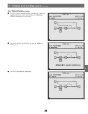
9 - Connected equipment loads will lose power if the bypass power source fails. 11 12 13 4 30 Display and Configuration (continued) 1 9-3-1 Status Display (continued) •2 The loads are supplied by bypass source due to initial startup of 2 the UPS. 3 4 5 2 •3 The UPS is starting up by battery power. 6 7 8 9 3 • 4 10 The UPS system is in auto bypass mode.
9 - Connected equipment loads will lose power if the bypass power source fails. 11 12 13 4 30 Display and Configuration (continued) 1 9-3-1 Status Display (continued) •2 The loads are supplied by bypass source due to initial startup of 2 the UPS. 3 4 5 2 •3 The UPS is starting up by battery power. 6 7 8 9 3 • 4 10 The UPS system is in auto bypass mode.
Owner's Manual for SU80K UPS 932793
Page 31
Connected equipment loads will receive battery backup power if the mains 2 (utility or generator) power source fails. 3 4 5 5 •6 The UPS is operating in battery backup mode. Display and Configuration (continued) 1 9-3-1 Status Display (continued) •5 The UPS system is in online (normal) mode. The loads are supplied by battery power. 6 7 8 6 9 •7 The UPS is performing the "battery test". 10 11 12 7 13 31 9 -
Connected equipment loads will receive battery backup power if the mains 2 (utility or generator) power source fails. 3 4 5 5 •6 The UPS is operating in battery backup mode. Display and Configuration (continued) 1 9-3-1 Status Display (continued) •5 The UPS system is in online (normal) mode. The loads are supplied by battery power. 6 7 8 6 9 •7 The UPS is performing the "battery test". 10 11 12 7 13 31 9 -
Owner's Manual for SU80K UPS 932793
Page 50
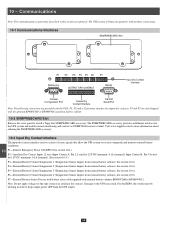
...Temperature 2 (Temperature Sensor Imputs from the UPS output. 13 50 Communications 1 Note: The communications connections described in order to install a Tripp Lite SNMPWEBCARD accessory. The SNMPWEBCARD accessory provides an Ethernet interface for 12V DC minimum, 0.1A (nominal); Damage to the repo contacts or ...12 P7-External Battery Status (For use with battery status cable supplied with the optional BP480V26P or BP480V40C matching battery cabinet. 8 10-2 SNMPWEBCARD Slot Remove the cover panel to keep output power OFF from external battery cabinets. Visit www.tripplite.com for more...
...Temperature 2 (Temperature Sensor Imputs from the UPS output. 13 50 Communications 1 Note: The communications connections described in order to install a Tripp Lite SNMPWEBCARD accessory. The SNMPWEBCARD accessory provides an Ethernet interface for 12V DC minimum, 0.1A (nominal); Damage to the repo contacts or ...12 P7-External Battery Status (For use with battery status cable supplied with the optional BP480V26P or BP480V40C matching battery cabinet. 8 10-2 SNMPWEBCARD Slot Remove the cover panel to keep output power OFF from external battery cabinets. Visit www.tripplite.com for more...

Owner's Manual for SU80K UPS 932793
Page 51
...P4, P5, P6) allow the UPS system to the EPO circuit enables remote emergency shutdown of external battery cabinets. Pin 5 = reference voltage. Supplied REPO button must then be a latching type and in a NC position. Pin 2 = detection cable connected; 10 - Connecting the UPS system...battery cabinet status signals through an optional cable. Pin 1 = +12V; Communications (continued) 1 10-4 Remote Emergency Power Off (EPO) Circuit Diagram The Remote Emergency Power Off (EPO) input connection (P1) allows you to connect the UPS system to receive signals from an optional accessory...
...P4, P5, P6) allow the UPS system to the EPO circuit enables remote emergency shutdown of external battery cabinets. Pin 5 = reference voltage. Supplied REPO button must then be a latching type and in a NC position. Pin 2 = detection cable connected; 10 - Connecting the UPS system...battery cabinet status signals through an optional cable. Pin 1 = +12V; Communications (continued) 1 10-4 Remote Emergency Power Off (EPO) Circuit Diagram The Remote Emergency Power Off (EPO) input connection (P1) allows you to connect the UPS system to receive signals from an optional accessory...

