
Quick Start Guide for PowerAlert Power Management Software 932755
Page 2
...network and shuts down your computer when it . You can monitor several types of Tripp L ite devices, including UPS systems with an SNMPWE B CA R D**, UPS systems... by advanced users only. Note: The cable connection is dynamic, PowerAlert Network Shutdown Agent must supply it detects a signal (typically an • on the network via PowerA lert L ocal ... R D*, UPS systems that appear on batteryŽ event) from www.tripplite.com/software. available USB or serial port. € Power A ler t Networ k Shutdown A gent: Windows X P, Windows Server 2003 R 2 (32-bit) or Windows V ista ...
...network and shuts down your computer when it . You can monitor several types of Tripp L ite devices, including UPS systems with an SNMPWE B CA R D**, UPS systems... by advanced users only. Note: The cable connection is dynamic, PowerAlert Network Shutdown Agent must supply it detects a signal (typically an • on the network via PowerA lert L ocal ... R D*, UPS systems that appear on batteryŽ event) from www.tripplite.com/software. available USB or serial port. € Power A ler t Networ k Shutdown A gent: Windows X P, Windows Server 2003 R 2 (32-bit) or Windows V ista ...

Owner's Manual for SU120KX2 3-Phase UPS 933141
Page 4
... moving or lifting the unit. • Operate the UPS system at any object on the circuit. Connection Warnings 9 • The power supply for minor position adjustments within the final installation area only. Read all instructions thoroughly before working on the unit, especially containers of a ...of this equipment in a level, structurally sound location. 4 • The UPS system is not connected to an AC supply. • If the UPS system receives power from the sides. • Do not attempt to unpack or move , install or operate the UPS systems described in this...
... moving or lifting the unit. • Operate the UPS system at any object on the circuit. Connection Warnings 9 • The power supply for minor position adjustments within the final installation area only. Read all instructions thoroughly before working on the unit, especially containers of a ...of this equipment in a level, structurally sound location. 4 • The UPS system is not connected to an AC supply. • If the UPS system receives power from the sides. • Do not attempt to unpack or move , install or operate the UPS systems described in this...
Owner's Manual for SU120KX2 3-Phase UPS 933141
Page 6
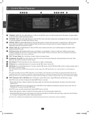
The primary AC input supply is still charging as required. "FAULT" LED: This red light illuminates when any UPS system or input power fault occurs. These buttons are opened and remain open for an extended period of time, the ...: • Main output and bypass output are turned off the alarm and places the UPS system in battery backup mode, discharging the batteries to provide power to recharge the batteries may cause irreversible battery damage. Control Panel Features 1 DCB A E 2 F GH I J K 3 4 • A 5 •B • C 6 • D • E 7 • F • G 8 &#...
The primary AC input supply is still charging as required. "FAULT" LED: This red light illuminates when any UPS system or input power fault occurs. These buttons are opened and remain open for an extended period of time, the ...: • Main output and bypass output are turned off the alarm and places the UPS system in battery backup mode, discharging the batteries to provide power to recharge the batteries may cause irreversible battery damage. Control Panel Features 1 DCB A E 2 F GH I J K 3 4 • A 5 •B • C 6 • D • E 7 • F • G 8 &#...

Owner's Manual for SU120KX2 3-Phase UPS 933141
Page 15
... the phase of each of the parallel port dip switches (either N+1 redundancy or capacity, must have the same rating, kVA capacity, and system and power module level firmware version (see Section 10-5-5 for cable size requirements. Wiring (continued) 1 6-7 AC Input/Output Wiring (Single UPS-SUS) (continued.... Connect each UPS must be parallel configured for each UPS parallel communication port(s) as shown in the diagram 1 . 9 10 11 DASHED LINES INDICATE USER-SUPPLIED PARTS AND CABLES. 1 12 13 12-212-93-3141.indb 15 14 15 12/28/2012 11:17:25 AM N + N - R S T...
... the phase of each of the parallel port dip switches (either N+1 redundancy or capacity, must have the same rating, kVA capacity, and system and power module level firmware version (see Section 10-5-5 for cable size requirements. Wiring (continued) 1 6-7 AC Input/Output Wiring (Single UPS-SUS) (continued.... Connect each UPS must be parallel configured for each UPS parallel communication port(s) as shown in the diagram 1 . 9 10 11 DASHED LINES INDICATE USER-SUPPLIED PARTS AND CABLES. 1 12 13 12-212-93-3141.indb 15 14 15 12/28/2012 11:17:25 AM N + N - R S T...

Owner's Manual for SU120KX2 3-Phase UPS 933141
Page 16
... individual UPS. (IP1 + OP1 = IP2 + OP2 = IP3 + OP3 = IP4 + OP4, minimum/maximum deviation must have the same rating, kVA capacity, and system and power module level firmware version (see Section 10-5-5 for either both ON (down) or both OFF (up) as shown in the diagram 1 . •2 Each UPS is...the other parallel-configured UPS in order to be < 10%). • Parallel configurations are operating in the diagram 1 . 6 7 8 9 10 11 DASHED LINES INDICATE USER-SUPPLIED PARTS AND CABLES. 1 12 13 14 16 12-212-93-3141.indb 16 12/28/2012 11:17:26 AM Do not attempt to configure...
... individual UPS. (IP1 + OP1 = IP2 + OP2 = IP3 + OP3 = IP4 + OP4, minimum/maximum deviation must have the same rating, kVA capacity, and system and power module level firmware version (see Section 10-5-5 for either both ON (down) or both OFF (up) as shown in the diagram 1 . •2 Each UPS is...the other parallel-configured UPS in order to be < 10%). • Parallel configurations are operating in the diagram 1 . 6 7 8 9 10 11 DASHED LINES INDICATE USER-SUPPLIED PARTS AND CABLES. 1 12 13 14 16 12-212-93-3141.indb 16 12/28/2012 11:17:26 AM Do not attempt to configure...
Owner's Manual for SU120KX2 3-Phase UPS 933141
Page 17
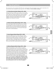
... rectifier converts incoming AC utility power to connected equipment. If the UPS system detects a bypass (reserve) power source that conforms to normal parameters, then the UPS system automatically switches to auto bypass mode to continue supplying power to DC power that the bypass source is required..., you can facilitate this and still maintain AC power to static internal bypass. After confirming that charges the batteries and supplies the inverter. This allows service technicians...
... rectifier converts incoming AC utility power to connected equipment. If the UPS system detects a bypass (reserve) power source that conforms to normal parameters, then the UPS system automatically switches to auto bypass mode to continue supplying power to DC power that the bypass source is required..., you can facilitate this and still maintain AC power to static internal bypass. After confirming that charges the batteries and supplies the inverter. This allows service technicians...

Owner's Manual for SU120KX2 3-Phase UPS 933141
Page 21
... screen will show "ON AUTO BYPASS", the "BYPASS" LED will illuminate and UPS system output will be supplied by Q4 Q2 7 the input power source via the bypass path. Q3 Off (open). If the AC input power source is normal, the UPS system is off and the "NORMAL" LED C will activate and synchronize...
... screen will show "ON AUTO BYPASS", the "BYPASS" LED will illuminate and UPS system output will be supplied by Q4 Q2 7 the input power source via the bypass path. Q3 Off (open). If the AC input power source is normal, the UPS system is off and the "NORMAL" LED C will activate and synchronize...
Owner's Manual for SU120KX2 3-Phase UPS 933141
Page 22
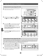
... button B until you hear a beep), then release the button. Before performing maintenance or repair on output circuit breaker Q4 to supply battery-derived power to the output circuit breaker. The UPS should transfer to Bypass Mode?". Do not proceed if it is ON; The "BATTERY"... LED B will activate and use stored DC battery power to supply AC power to the connected equipment. 9 Output B Manual Bypass Bypass Input Main Input A Q4 10 Output Manual Bypass Main 4 Bypass Input Input...
... button B until you hear a beep), then release the button. Before performing maintenance or repair on output circuit breaker Q4 to supply battery-derived power to the output circuit breaker. The UPS should transfer to Bypass Mode?". Do not proceed if it is ON; The "BATTERY"... LED B will activate and use stored DC battery power to supply AC power to the connected equipment. 9 Output B Manual Bypass Bypass Input Main Input A Q4 10 Output Manual Bypass Main 4 Bypass Input Input...

Owner's Manual for SU120KX2 3-Phase UPS 933141
Page 32
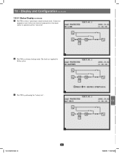
Connected equipment loads will lose power if the bypass power source fails. 11 12 13 4 14 32 12-212-93-3141.indb 32 12/28/2012 11:18:00 AM Display and Configuration (continued) 1 10-3-1 Status Display (continued) •2 The loads are supplied by bypass source due to initial startup of 2 the UPS. 3 4 5 2 •3 The UPS is starting up by battery power. 6 7 8 9 3 • 4 10 The UPS system is in auto bypass mode. 10 -
Connected equipment loads will lose power if the bypass power source fails. 11 12 13 4 14 32 12-212-93-3141.indb 32 12/28/2012 11:18:00 AM Display and Configuration (continued) 1 10-3-1 Status Display (continued) •2 The loads are supplied by bypass source due to initial startup of 2 the UPS. 3 4 5 2 •3 The UPS is starting up by battery power. 6 7 8 9 3 • 4 10 The UPS system is in auto bypass mode. 10 -
Owner's Manual for SU120KX2 3-Phase UPS 933141
Page 33
The loads are supplied by battery power. 6 •7 The UPS is in online (normal) mode. Display and Configuration (continued) 10-3-1 Status Display (continued) •5 The UPS system is operating in battery backup mode. Connected equipment loads will receive battery backup power if the mains (utility or generator) power source fails. 5 •6 The UPS is performing the "battery test". 12-212-93-3141.indb 33 7 33 1 2 3 4 5 6 7 8 9 10 11 12 13 14 12/28/2012 11:18:01 AM 10 -
The loads are supplied by battery power. 6 •7 The UPS is in online (normal) mode. Display and Configuration (continued) 10-3-1 Status Display (continued) •5 The UPS system is operating in battery backup mode. Connected equipment loads will receive battery backup power if the mains (utility or generator) power source fails. 5 •6 The UPS is performing the "battery test". 12-212-93-3141.indb 33 7 33 1 2 3 4 5 6 7 8 9 10 11 12 13 14 12/28/2012 11:18:01 AM 10 -
Owner's Manual for SU120KX2 3-Phase UPS 933141
Page 52
...See Section 11-6.) P7-External Battery Status (For use with battery status cable supplied with the UPS: P1, P2 and a 12 position strip for 12V DC...closure signals that allow the UPS system to receive commands and monitor external battery conditions: 10 P1-Remote Emergency Power Off (EPO) (See Section 11-4.) P2-Auxiliary Dry Contact Inputs (2 sets) (Input Contact A: Pin 1,2...12 Note: Do not apply voltages to install a Tripp Lite SNMPWEBCARD or MODBUSCARD accessory. Input Contact B: Pin 3,4 Rated for the output dry contacts. Damage to keep output power OFF from the UPS output. 13 14 52 12...
...See Section 11-6.) P7-External Battery Status (For use with battery status cable supplied with the UPS: P1, P2 and a 12 position strip for 12V DC...closure signals that allow the UPS system to receive commands and monitor external battery conditions: 10 P1-Remote Emergency Power Off (EPO) (See Section 11-4.) P2-Auxiliary Dry Contact Inputs (2 sets) (Input Contact A: Pin 1,2...12 Note: Do not apply voltages to install a Tripp Lite SNMPWEBCARD or MODBUSCARD accessory. Input Contact B: Pin 3,4 Rated for the output dry contacts. Damage to keep output power OFF from the UPS output. 13 14 52 12...

Owner's Manual for SU120KX2 3-Phase UPS 933141
Page 53
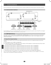
...open . Pin 3 = battery cabinet breaker status (signal active= breaker on -line mode. Pin 5 = reference voltage. P1 DC 3 4 USER-SUPPLIED REPO - LATCHING SWITCH 5 11-5 Auxiliary Dry Contact Input Circuit Diagram The auxiliary dry contact input connections (P2) allow the UPS system to your ...INPUT DRY B. 7 These contacts are normally open . User supplied REPO button must then be latching type in a closed position. Communications (continued) 1 11-4 Remote Emergency Power Off (EPO) Circuit Diagram The Remote Emergency Power Off (EPO) input connection (P1) allows you to connect ...
...open . Pin 3 = battery cabinet breaker status (signal active= breaker on -line mode. Pin 5 = reference voltage. P1 DC 3 4 USER-SUPPLIED REPO - LATCHING SWITCH 5 11-5 Auxiliary Dry Contact Input Circuit Diagram The auxiliary dry contact input connections (P2) allow the UPS system to your ...INPUT DRY B. 7 These contacts are normally open . User supplied REPO button must then be latching type in a closed position. Communications (continued) 1 11-4 Remote Emergency Power Off (EPO) Circuit Diagram The Remote Emergency Power Off (EPO) input connection (P1) allows you to connect ...

