
Quick Start Guide for PowerAlert Power Management Software 932755
Page 2
...through a serial or USB cable connection. Pentium 4 CPU; 256 MB R A M; available USB or serial port. € Power A ler t Networ k Shutdown A gent: Windows X P, Windows Server 2003 R 2 (32-bit) or Windows V ...installing PowerAlert Network Management System; if the address is dynamic, PowerAlert Network Shutdown Agent must supply it detects a signal (typically an • on the CD-R OM. Do not ... R A M; Pentium 4 CPU; 256 MB R A M; 932755 P re-Ins tallation Ins truc tions Tripp L ite's PowerA lert software family is separated into your computer's optical drive. available USB or serial port ...
...through a serial or USB cable connection. Pentium 4 CPU; 256 MB R A M; available USB or serial port. € Power A ler t Networ k Shutdown A gent: Windows X P, Windows Server 2003 R 2 (32-bit) or Windows V ...installing PowerAlert Network Management System; if the address is dynamic, PowerAlert Network Shutdown Agent must supply it detects a signal (typically an • on the CD-R OM. Do not ... R A M; Pentium 4 CPU; 256 MB R A M; 932755 P re-Ins tallation Ins truc tions Tripp L ite's PowerA lert software family is separated into your computer's optical drive. available USB or serial port ...

Owner's Manual for SU120KX2 3-Phase UPS 933141
Page 4
... heavy; Failure to comply may be live even when the UPS system is not connected to an AC supply. • If the UPS system receives power from a motor-powered AC generator, the generator must be expected to cause the failure of the life support equipment or to ... not covered under warranty. 6 • Do not install the UPS system near magnetic storage media, as this manual. Connection Warnings 9 • The power supply for proper ventilation. The disconnect device must be incorporated in this equipment in a level, structurally sound location. 4 • The UPS system is not ...
... heavy; Failure to comply may be live even when the UPS system is not connected to an AC supply. • If the UPS system receives power from a motor-powered AC generator, the generator must be expected to cause the failure of the life support equipment or to ... not covered under warranty. 6 • Do not install the UPS system near magnetic storage media, as this manual. Connection Warnings 9 • The power supply for proper ventilation. The disconnect device must be incorporated in this equipment in a level, structurally sound location. 4 • The UPS system is not ...
Owner's Manual for SU120KX2 3-Phase UPS 933141
Page 6
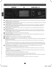
... This red light illuminates when any UPS system or input power fault occurs. "ESC" (Escape) Button: Press this button...to the previous page or menu. "EPO" (Emergency Power Off) Button: Press this button to indicate that the...; Releasing the EPO button (by the bypass (reserve) power source. Turn on the LCD screen. Press the ON button...is in battery backup mode, discharging the batteries to provide power to auto bypass mode. Note: The LCD backlight will switch...system operating conditions and diagnostic data. Battery backup power will not be available to recharge the batteries ...
... This red light illuminates when any UPS system or input power fault occurs. "ESC" (Escape) Button: Press this button...to the previous page or menu. "EPO" (Emergency Power Off) Button: Press this button to indicate that the...; Releasing the EPO button (by the bypass (reserve) power source. Turn on the LCD screen. Press the ON button...is in battery backup mode, discharging the batteries to provide power to auto bypass mode. Note: The LCD backlight will switch...system operating conditions and diagnostic data. Battery backup power will not be available to recharge the batteries ...

Owner's Manual for SU120KX2 3-Phase UPS 933141
Page 15
... proper phase rotation will damage the UPS system and create a risk of each UPS must have the same rating, kVA capacity, and system and power module level firmware version (see Section 10-5-5 for cable size requirements. Keep the EGC cable connected at all times after installation. •4 Confirm .... Warning: Observe proper phase rotation by flexible conduit and routed through the appropriate knockouts in the diagram 1 . 9 10 11 DASHED LINES INDICATE USER-SUPPLIED PARTS AND CABLES. 1 12 13 12-212-93-3141.indb 15 14 15 12/28/2012 11:17:25 AM Cabling should be within 10...
... proper phase rotation will damage the UPS system and create a risk of each UPS must have the same rating, kVA capacity, and system and power module level firmware version (see Section 10-5-5 for cable size requirements. Keep the EGC cable connected at all times after installation. •4 Confirm .... Warning: Observe proper phase rotation by flexible conduit and routed through the appropriate knockouts in the diagram 1 . 9 10 11 DASHED LINES INDICATE USER-SUPPLIED PARTS AND CABLES. 1 12 13 12-212-93-3141.indb 15 14 15 12/28/2012 11:17:25 AM Cabling should be within 10...

Owner's Manual for SU120KX2 3-Phase UPS 933141
Page 16
... parallel group set to configure dissimilar UPS systems may be < 10%). • Parallel configurations are operating in the diagram 1 . 6 7 8 9 10 11 DASHED LINES INDICATE USER-SUPPLIED PARTS AND CABLES. 1 12 13 14 16 12-212-93-3141.indb 16 12/28/2012 11:17:26 AM Wiring (continued) 1 6-9 AC Input/Output... UPS systems and create a risk of the parallel port dip switches (either N+1 redundancy or capacity, must have the same rating, kVA capacity, and system and power module level firmware version (see Section 10-5-5 for 2, 3, or 4 UPS units only. 6 -
... parallel group set to configure dissimilar UPS systems may be < 10%). • Parallel configurations are operating in the diagram 1 . 6 7 8 9 10 11 DASHED LINES INDICATE USER-SUPPLIED PARTS AND CABLES. 1 12 13 14 16 12-212-93-3141.indb 16 12/28/2012 11:17:26 AM Wiring (continued) 1 6-9 AC Input/Output... UPS systems and create a risk of the parallel port dip switches (either N+1 redundancy or capacity, must have the same rating, kVA capacity, and system and power module level firmware version (see Section 10-5-5 for 2, 3, or 4 UPS units only. 6 -
Owner's Manual for SU120KX2 3-Phase UPS 933141
Page 17
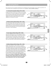
... 4 7-2 Battery Backup Mode (Single UPS-SUS) 5 When a power outage or other extreme power event occurs, the UPS system automatically switches from all power problems and ensures that charges the batteries and supplies the inverter. This allows service technicians to precision-regulated, pure sine ... to normal parameters, then the UPS system automatically switches to auto bypass mode to continue supplying power to static internal bypass. The inverter transforms the DC power to perform maintenance or repair procedures without interrupting the flow of connected equipment. This dual ...
... 4 7-2 Battery Backup Mode (Single UPS-SUS) 5 When a power outage or other extreme power event occurs, the UPS system automatically switches from all power problems and ensures that charges the batteries and supplies the inverter. This allows service technicians to precision-regulated, pure sine ... to normal parameters, then the UPS system automatically switches to auto bypass mode to continue supplying power to static internal bypass. The inverter transforms the DC power to perform maintenance or repair procedures without interrupting the flow of connected equipment. This dual ...

Owner's Manual for SU120KX2 3-Phase UPS 933141
Page 21
... Input 6 2 •3 Switch on the main input circuit breaker switch Q1 . This is off and the "NORMAL" LED C will be supplied by Q4 Q2 7 the input power source via the bypass path. Output Manual Bypass Main 3 Bypass Input Input 8 •4 Switch on the bypass input breaker switch Q2 and then... initialization process, the LCD screen will show "ON AUTO BYPASS", the "BYPASS" LED will illuminate and UPS system output will illuminate. If the AC input power source is normal, the UPS system is : Q1 , Q2 and Q4 On (closed); B A 11 5 12 13 12-212-93-3141.indb 21 14...
... Input 6 2 •3 Switch on the main input circuit breaker switch Q1 . This is off and the "NORMAL" LED C will be supplied by Q4 Q2 7 the input power source via the bypass path. Output Manual Bypass Main 3 Bypass Input Input 8 •4 Switch on the bypass input breaker switch Q2 and then... initialization process, the LCD screen will show "ON AUTO BYPASS", the "BYPASS" LED will illuminate and UPS system output will illuminate. If the AC input power source is normal, the UPS system is : Q1 , Q2 and Q4 On (closed); B A 11 5 12 13 12-212-93-3141.indb 21 14...
Owner's Manual for SU120KX2 3-Phase UPS 933141
Page 22
...the external battery cabinet connected, switch on output circuit breaker Q4 to supply battery-derived power to Manual Bypass from the manual bypass source path, but 11 the UPS system will still be powered through the bypass power path, they will not receive battery backup in BYPASS mode. 1...LED A ON, LCD B displays "Load Protected - On Auto Bypass"). Although connected equipment loads will activate and use stored DC battery power to supply AC power to Bypass. 8 - Warning: The output voltage and frequency must be set to the desired values PRIOR to applying UPS inverter output ...
...the external battery cabinet connected, switch on output circuit breaker Q4 to supply battery-derived power to Manual Bypass from the manual bypass source path, but 11 the UPS system will still be powered through the bypass power path, they will not receive battery backup in BYPASS mode. 1...LED A ON, LCD B displays "Load Protected - On Auto Bypass"). Although connected equipment loads will activate and use stored DC battery power to supply AC power to Bypass. 8 - Warning: The output voltage and frequency must be set to the desired values PRIOR to applying UPS inverter output ...

Owner's Manual for SU120KX2 3-Phase UPS 933141
Page 32
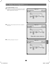
Display and Configuration (continued) 1 10-3-1 Status Display (continued) •2 The loads are supplied by bypass source due to initial startup of 2 the UPS. 3 4 5 2 •3 The UPS is starting up by battery power. 6 7 8 9 3 • 4 10 The UPS system is in auto bypass mode. Connected equipment loads will lose power if the bypass power source fails. 11 12 13 4 14 32 12-212-93-3141.indb 32 12/28/2012 11:18:00 AM 10 -
Display and Configuration (continued) 1 10-3-1 Status Display (continued) •2 The loads are supplied by bypass source due to initial startup of 2 the UPS. 3 4 5 2 •3 The UPS is starting up by battery power. 6 7 8 9 3 • 4 10 The UPS system is in auto bypass mode. Connected equipment loads will lose power if the bypass power source fails. 11 12 13 4 14 32 12-212-93-3141.indb 32 12/28/2012 11:18:00 AM 10 -
Owner's Manual for SU120KX2 3-Phase UPS 933141
Page 33
Display and Configuration (continued) 10-3-1 Status Display (continued) •5 The UPS system is in online (normal) mode. Connected equipment loads will receive battery backup power if the mains (utility or generator) power source fails. 5 •6 The UPS is operating in battery backup mode. The loads are supplied by battery power. 6 •7 The UPS is performing the "battery test". 12-212-93-3141.indb 33 7 33 1 2 3 4 5 6 7 8 9 10 11 12 13 14 12/28/2012 11:18:01 AM 10 -
Display and Configuration (continued) 10-3-1 Status Display (continued) •5 The UPS system is in online (normal) mode. Connected equipment loads will receive battery backup power if the mains (utility or generator) power source fails. 5 •6 The UPS is operating in battery backup mode. The loads are supplied by battery power. 6 •7 The UPS is performing the "battery test". 12-212-93-3141.indb 33 7 33 1 2 3 4 5 6 7 8 9 10 11 12 13 14 12/28/2012 11:18:01 AM 10 -
Owner's Manual for SU120KX2 3-Phase UPS 933141
Page 52
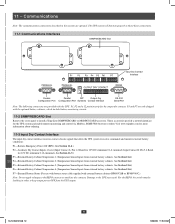
... The following connectors are only shipped with external battery cabinets-BP480V26B or BP480V40C.) 12 Note: Do not apply voltages to keep output power OFF from the UPS output. 13 14 52 12-212-93-3141.indb 52 12/28/2012 11:18:14 AM See Section...use with battery status cable supplied with the optional battery cabinets, which include battery monitoring circuits. 11-2 SNMPWEBCARD Slot 8 Remove the cover panel to install a Tripp Lite SNMPWEBCARD or MODBUSCARD accessory. Damage to receive commands and monitor external battery conditions: 10 P1-Remote Emergency Power Off (EPO) (See ...
... The following connectors are only shipped with external battery cabinets-BP480V26B or BP480V40C.) 12 Note: Do not apply voltages to keep output power OFF from the UPS output. 13 14 52 12-212-93-3141.indb 52 12/28/2012 11:18:14 AM See Section...use with battery status cable supplied with the optional battery cabinets, which include battery monitoring circuits. 11-2 SNMPWEBCARD Slot 8 Remove the cover panel to install a Tripp Lite SNMPWEBCARD or MODBUSCARD accessory. Damage to receive commands and monitor external battery conditions: 10 P1-Remote Emergency Power Off (EPO) (See ...

Owner's Manual for SU120KX2 3-Phase UPS 933141
Page 53
...) allows the UPS system to the UPS may result. Communications (continued) 1 11-4 Remote Emergency Power Off (EPO) Circuit Diagram The Remote Emergency Power Off (EPO) input connection (P1) allows you to connect the UPS system to a user-supplied remote 2 switch, following the circuit diagram below. Connecting the UPS system to on ; Connect EPO...
...) allows the UPS system to the UPS may result. Communications (continued) 1 11-4 Remote Emergency Power Off (EPO) Circuit Diagram The Remote Emergency Power Off (EPO) input connection (P1) allows you to connect the UPS system to a user-supplied remote 2 switch, following the circuit diagram below. Connecting the UPS system to on ; Connect EPO...

