
Product Specification
Page 15
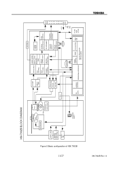
XM-7002B Rev.1.0 Figure 5 Basic configuration of XM-7002B 11/27 XM-7002B BLOCK DIAGRAM D ISC MOTOR PUH MO DRIVER EJECT SW FEED MOTOR POSITION DETECTOR DRAWER RELEASE DETECTOR B USY LED SOLENOID EJECT MUTING RF AMP SERVO AMP Eject TRACKING F OCUS Feed-Mo EFM ... DAC EFFECT RAM VCO 17/34 MHz ERROR CORRECTION SERVO CONTROL MASTER CLOCK GEN. 33.86 MHz D-RAM 128 kB CD-ROM DATA SYNC DETECT CONTROL DE-SCRAMBLE HEADER DETECT ERROR CORRECTION IDE/ATAPI INTERFACE CONTROL 50 MHz + 5 V GND FN CONV. ACCESS CONTROL PERIPHERAL INTERFACE TIMING CONTROL TIMER INT.CONTROL RAM 2 kB...
XM-7002B Rev.1.0 Figure 5 Basic configuration of XM-7002B 11/27 XM-7002B BLOCK DIAGRAM D ISC MOTOR PUH MO DRIVER EJECT SW FEED MOTOR POSITION DETECTOR DRAWER RELEASE DETECTOR B USY LED SOLENOID EJECT MUTING RF AMP SERVO AMP Eject TRACKING F OCUS Feed-Mo EFM ... DAC EFFECT RAM VCO 17/34 MHz ERROR CORRECTION SERVO CONTROL MASTER CLOCK GEN. 33.86 MHz D-RAM 128 kB CD-ROM DATA SYNC DETECT CONTROL DE-SCRAMBLE HEADER DETECT ERROR CORRECTION IDE/ATAPI INTERFACE CONTROL 50 MHz + 5 V GND FN CONV. ACCESS CONTROL PERIPHERAL INTERFACE TIMING CONTROL TIMER INT.CONTROL RAM 2 kB...
Product Specification
Page 17
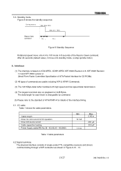
...standby mode. (a stop spindle motor) 6. 5.3. After 24 seconds (default value), it move onto 4.4 to the standard of ATA/ATAPI-4 for 5V operation Driver IoH source current Cable capacitive loading Power Supply cablesPIN No.38 - 42(+B),43 - 45(GND) Min 12 mA 1.5 A Max 0.46 m -400 µ... for CD-ROMs) (2) 48 types of single ended TTL compatible receivers and drivers communicating through a 50P-conductor as shown in 8 seconds of the interface timing. 6.1. The data length for each block is changeable by command. (5) Please refer to 10X mode in Figure 9,10 - 13. 13/27 XM-7002B Rev.1.0...
...standby mode. (a stop spindle motor) 6. 5.3. After 24 seconds (default value), it move onto 4.4 to the standard of ATA/ATAPI-4 for 5V operation Driver IoH source current Cable capacitive loading Power Supply cablesPIN No.38 - 42(+B),43 - 45(GND) Min 12 mA 1.5 A Max 0.46 m -400 µ... for CD-ROMs) (2) 48 types of single ended TTL compatible receivers and drivers communicating through a 50P-conductor as shown in 8 seconds of the interface timing. 6.1. The data length for each block is changeable by command. (5) Please refer to 10X mode in Figure 9,10 - 13. 13/27 XM-7002B Rev.1.0...
Product Specification
Page 21
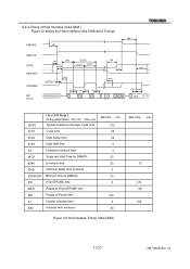
... 20 0 20 0 100 0 20 Figure 12 Host Interface Timing (Ultra DMA) Max time (ns) 70 170 50 150 17/27 XM-7002B Rev.1.0 tENV Envelope time t2AD Minimum Delay time for Driver t2IORODY Minimum time for DMACK- 6.2.4.Timing of Host Interface (Ultra DMA ) Figure 12 shows the Host Interface Ultra DMA word Timings...
... 20 0 20 0 100 0 20 Figure 12 Host Interface Timing (Ultra DMA) Max time (ns) 70 170 50 150 17/27 XM-7002B Rev.1.0 tENV Envelope time t2AD Minimum Delay time for Driver t2IORODY Minimum time for DMACK- 6.2.4.Timing of Host Interface (Ultra DMA ) Figure 12 shows the Host Interface Ultra DMA word Timings...