
User Manual
Page 122
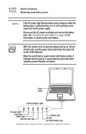
Power button System Indicator Lights AC power light On/off light ( ), and the power button light (near the upper left corner of the keyboard. Disconnect the AC power cord/cable and remove the battery pack. When the on/off light or power button light flashes amber, it is ... HINT: Be careful not to confuse the battery light ( ), the on/ off light Battery light Hard disk drive light Wireless light SD light (on replacing the main battery. 122 Mobile Computing Monitoring main battery power NOTE If the AC power light flashes amber during charging, either the battery pack is...
Power button System Indicator Lights AC power light On/off light ( ), and the power button light (near the upper left corner of the keyboard. Disconnect the AC power cord/cable and remove the battery pack. When the on/off light or power button light flashes amber, it is ... HINT: Be careful not to confuse the battery light ( ), the on/ off light Battery light Hard disk drive light Wireless light SD light (on replacing the main battery. 122 Mobile Computing Monitoring main battery power NOTE If the AC power light flashes amber during charging, either the battery pack is...
User Manual
Page 192
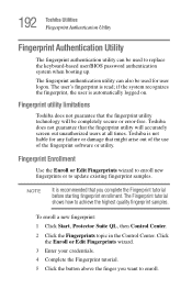
.... 4 Complete the Fingerprint tutorial. 5 Click the button above the finger you complete the Fingerprint tutorial before starting fingerprint enrollment. Toshiba is recommended that might arise out of the use of the fingerprint software or utility. To enroll a new fingerprint: 1 Click... user is read; NOTE It is not liable for user logon. 192 Toshiba Utilities Fingerprint Authentication Utility Fingerprint Authentication Utility The fingerprint authentication utility can also be used to replace the keyboard-based user/BIOS password authentication system when booting up.
.... 4 Complete the Fingerprint tutorial. 5 Click the button above the finger you complete the Fingerprint tutorial before starting fingerprint enrollment. Toshiba is recommended that might arise out of the use of the fingerprint software or utility. To enroll a new fingerprint: 1 Click... user is read; NOTE It is not liable for user logon. 192 Toshiba Utilities Fingerprint Authentication Utility Fingerprint Authentication Utility The fingerprint authentication utility can also be used to replace the keyboard-based user/BIOS password authentication system when booting up.
User Manual
Page 219
... press Fn and F10 simultaneously to turn off the cursor control mode light or Fn and F11 simultaneously to the keyboard itself. A keypad overlay may be replaced. Keyboard problems If, when you connected may be defective or incompatible with your computer, and for all batteries. If the ...problem occurs when both the keypad overlays are using is on the most recent software and hardware options for your computer, or visit the Toshiba ...
... press Fn and F10 simultaneously to turn off the cursor control mode light or Fn and F11 simultaneously to the keyboard itself. A keypad overlay may be replaced. Keyboard problems If, when you connected may be defective or incompatible with your computer, and for all batteries. If the ...problem occurs when both the keypad overlays are using is on the most recent software and hardware options for your computer, or visit the Toshiba ...
Maintenance Manual
Page 4
...Chapter 1 Hardware Overview describes the TECRA A8 series / Satellite Pro A120 series system unit and each FRU. The manual is divided into the following : ‰ Handling the LCD module ‰ Board layout ‰ Pin assignments ‰ Keyboard scan/character codes ‰ ...Key layout ‰ Wiring diagrams ‰ BIOS rewrite procedures ‰ EC/KBC rewrite procedures ‰ Reliability iv [CONFIDENTIAL] TECRA A8 /Satellite Pro A120 Maintenance Manual (960-573) Chapter 4 Replacement Procedures describes the removal and...
...Chapter 1 Hardware Overview describes the TECRA A8 series / Satellite Pro A120 series system unit and each FRU. The manual is divided into the following : ‰ Handling the LCD module ‰ Board layout ‰ Pin assignments ‰ Keyboard scan/character codes ‰ ...Key layout ‰ Wiring diagrams ‰ BIOS rewrite procedures ‰ EC/KBC rewrite procedures ‰ Reliability iv [CONFIDENTIAL] TECRA A8 /Satellite Pro A120 Maintenance Manual (960-573) Chapter 4 Replacement Procedures describes the removal and...
Maintenance Manual
Page 8
Chapter 4 Replacement Procedures 4.1 General...4-1 4.2 Battery pack ...4-8 4.3 PC card...4-10 4.4 SD card...4-11 4.5 HDD...4-12 4.6 MDC/Memory module 4-16 4.7 Keyboard...4-19 4.8 Optical drive...4-22 4.9 Wireless LAN card 4-25 4.10 Cover assembly...4-27 4.11 SW membrane...4-31 4.12 Fingerprint sensor board 4-33 4.13 Touch pad...4-35 4.... ...4-62 4.27 Display rear cover ...4-63 4.28 Wireless LAN antenna/Bluetooth antenna 4-65 4.29 Hinge...4-71 4.30 Speaker...4-73 4.31 Fluorescent Lamp...4-77 viii [CONFIDENTIAL] TECRA A8 /Satellite Pro A120 Maintenance Manual (960-573)
Chapter 4 Replacement Procedures 4.1 General...4-1 4.2 Battery pack ...4-8 4.3 PC card...4-10 4.4 SD card...4-11 4.5 HDD...4-12 4.6 MDC/Memory module 4-16 4.7 Keyboard...4-19 4.8 Optical drive...4-22 4.9 Wireless LAN card 4-25 4.10 Cover assembly...4-27 4.11 SW membrane...4-31 4.12 Fingerprint sensor board 4-33 4.13 Touch pad...4-35 4.... ...4-62 4.27 Display rear cover ...4-63 4.28 Wireless LAN antenna/Bluetooth antenna 4-65 4.29 Hinge...4-71 4.30 Speaker...4-73 4.31 Fluorescent Lamp...4-77 viii [CONFIDENTIAL] TECRA A8 /Satellite Pro A120 Maintenance Manual (960-573)
Maintenance Manual
Page 49
...Chapter 4) 2. Power Supply 2. Modem 9. NOTE: Before replacing the system board, it is causing the computer to malfunction. Also, following implements are : 1. Implements for debugging port check • Toshiba DOS system FD • RS-232C cross cable •... 2 describes how to determine if a Field Replaceable Unit (FRU) in Appendix H "EC/KBC Rewrite Procedures". The FRUs covered are necessary: 1. Keyboard/Touch pad 6. Display 7. Optical Drive 8. Bluetooth 11. The implement for displaying debug port test result TECRA A8 /Satellite Pro A120 Maintenance Manual (960-573)...
...Chapter 4) 2. Power Supply 2. Modem 9. NOTE: Before replacing the system board, it is causing the computer to malfunction. Also, following implements are : 1. Implements for debugging port check • Toshiba DOS system FD • RS-232C cross cable •... 2 describes how to determine if a Field Replaceable Unit (FRU) in Appendix H "EC/KBC Rewrite Procedures". The FRUs covered are necessary: 1. Keyboard/Touch pad 6. Display 7. Optical Drive 8. Bluetooth 11. The implement for displaying debug port test result TECRA A8 /Satellite Pro A120 Maintenance Manual (960-573)...

Maintenance Manual
Page 101
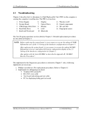
... 2: Connector Check and Replacement Check Procedure 1 Diagnostic Test Program Execution Check Execute the Keyboard Test in the Diagnostic Program. 2.7 Keyboard and Touch pad Troubleshooting 2 Troubleshooting Procedures 2.7 Keyboard and Touch pad Troubleshooting To determine if the computer's keyboard or touch pad is functioning... Start with Procedure 1 and continue with the other procedures as instructed. TECRA A8 /Satellite Pro A120 Maintenance Manual (960-573) [CONFIDENTIAL] 2-53 If an error does not occur, the keyboard is functioning properly, perform the following procedures.
... 2: Connector Check and Replacement Check Procedure 1 Diagnostic Test Program Execution Check Execute the Keyboard Test in the Diagnostic Program. 2.7 Keyboard and Touch pad Troubleshooting 2 Troubleshooting Procedures 2.7 Keyboard and Touch pad Troubleshooting To determine if the computer's keyboard or touch pad is functioning... Start with Procedure 1 and continue with the other procedures as instructed. TECRA A8 /Satellite Pro A120 Maintenance Manual (960-573) [CONFIDENTIAL] 2-53 If an error does not occur, the keyboard is functioning properly, perform the following procedures.

Maintenance Manual
Page 102
...perform Check 5. 2-54 [CONFIDENTIAL] TECRA A8 /Satellite Pro A120 Maintenance Manual (960-573) If the SW membrane malfunctions, start with Check 1. 2. Check 4 The touch pad may be disconnected or damaged. Check 1 Make sure the keyboard cable is loose, reconnect firmly and ..., perform Check 8. If the keyboard malfunctions, start with a new one following the instructions in Chapter 4, Replacement Procedures. If the touch pad malfunctions, start with Check 6. Replace it with a new one following the instructions in Chapter 4, Replacement Procedures, and perform the following ...
...perform Check 5. 2-54 [CONFIDENTIAL] TECRA A8 /Satellite Pro A120 Maintenance Manual (960-573) If the SW membrane malfunctions, start with Check 1. 2. Check 4 The touch pad may be disconnected or damaged. Check 1 Make sure the keyboard cable is loose, reconnect firmly and ..., perform Check 8. If the keyboard malfunctions, start with a new one following the instructions in Chapter 4, Replacement Procedures. If the touch pad malfunctions, start with Check 6. Replace it with a new one following the instructions in Chapter 4, Replacement Procedures, and perform the following ...

Maintenance Manual
Page 103
...is still an error, go to procedure 1. Check 8 The system board may be damaged. Replace it with a new one following the instructions in Chapter 4, Replacement Procedures. TECRA A8 /Satellite Pro A120 Maintenance Manual (960-573) [CONFIDENTIAL] 2-55 If there is loose, ...SW cable is firmly connected to Check 7. Replace it with a new one following the instructions in Chapter 4, Replacement Procedures. If the problem still exists, perform Check 8. Check 7 The SW membrane may be damaged. 2.7 Keyboard and Touch pad Troubleshooting 2 Troubleshooting Procedures Check ...
...is still an error, go to procedure 1. Check 8 The system board may be damaged. Replace it with a new one following the instructions in Chapter 4, Replacement Procedures. TECRA A8 /Satellite Pro A120 Maintenance Manual (960-573) [CONFIDENTIAL] 2-55 If there is loose, ...SW cable is firmly connected to Check 7. Replace it with a new one following the instructions in Chapter 4, Replacement Procedures. If the problem still exists, perform Check 8. Check 7 The SW membrane may be damaged. 2.7 Keyboard and Touch pad Troubleshooting 2 Troubleshooting Procedures Check ...
Maintenance Manual
Page 243
4 Replacement Procedures Chapter 4 Contents 4.1 General...4-1 4.2 Battery pack ...4-8 4.3 PC card...4-10 4.4 SD card...4-11 4.5 HDD...4-12 4.6 MDC/Memory module 4-16 4.7 Keyboard...4-19 4.8 Optical drive ...4-22 4.9 Wireless LAN card 4-25 4.10 Cover assembly...4-27 4.11 SW membrane...4-31 4.12 Fingerprint sensor board 4-33 4.13 Touch pad...4-35 4..../FL inverter 4-57 4.26 Cover latch ...4-62 4.27 Display rear cover ...4-63 4.28 Wireless LAN antenna/Bluetooth antenna 4-65 4.29 Hinge...4-71 4.30 Speaker...4-73 TECRA A8 /Satellite Pro A120 Maintenance Manual (960-573) [CONFIDENTIAL] 2-iii
4 Replacement Procedures Chapter 4 Contents 4.1 General...4-1 4.2 Battery pack ...4-8 4.3 PC card...4-10 4.4 SD card...4-11 4.5 HDD...4-12 4.6 MDC/Memory module 4-16 4.7 Keyboard...4-19 4.8 Optical drive ...4-22 4.9 Wireless LAN card 4-25 4.10 Cover assembly...4-27 4.11 SW membrane...4-31 4.12 Fingerprint sensor board 4-33 4.13 Touch pad...4-35 4..../FL inverter 4-57 4.26 Cover latch ...4-62 4.27 Display rear cover ...4-63 4.28 Wireless LAN antenna/Bluetooth antenna 4-65 4.29 Hinge...4-71 4.30 Speaker...4-73 TECRA A8 /Satellite Pro A120 Maintenance Manual (960-573) [CONFIDENTIAL] 2-iii

Maintenance Manual
Page 244
... 15.4-inch WXGA LG Philips Fluorescent Lamp........ 4-78 4.31.2 Replacing the 15.4-inch WXGA Samsung Fluorescent Lamp........... 4-87 Figures Figure 4-1 Figure 4-2 Figure 4-3 Figure 4-4 Figure 4-5 Figure... the HDD and HDD holder 4-14 Removing the MDC 4-16 Removing the memory module 4-17 Removing the keyboard (1 4-19 Removing the keyboard (2 4-20 Removing the optical drive 4-22 Disassembling the optical drive 4-23 Removing the wireless LAN card ...the serial/s-video board 4-41 Removing the RTC battery 4-43 4-iv [CONFIDENTIAL] TECRA A8 /Satellite Pro A120 Maintenance Manual (960-573)
... 15.4-inch WXGA LG Philips Fluorescent Lamp........ 4-78 4.31.2 Replacing the 15.4-inch WXGA Samsung Fluorescent Lamp........... 4-87 Figures Figure 4-1 Figure 4-2 Figure 4-3 Figure 4-4 Figure 4-5 Figure... the HDD and HDD holder 4-14 Removing the MDC 4-16 Removing the memory module 4-17 Removing the keyboard (1 4-19 Removing the keyboard (2 4-20 Removing the optical drive 4-22 Disassembling the optical drive 4-23 Removing the wireless LAN card ...the serial/s-video board 4-41 Removing the RTC battery 4-43 4-iv [CONFIDENTIAL] TECRA A8 /Satellite Pro A120 Maintenance Manual (960-573)

Maintenance Manual
Page 265
... 2. Lift the top edge of the keyboard while releasing the hook and turn the keyboard face down on either side and remove the keyboard holder. 4. Open the display and make it flat. 3. 4.7 Keyboard 4 Replacement Procedures 4.7 Keyboard Removing the Keyboard To remove the keyboard, follow the steps below and refer to...securing the keyboard. • M2.5×4B FLAT HEAD screw ×2 5. Insert your finger tip into the slit on the palm rest. Keyboard holder Slit M2.5×4B FLAT HEAD Slit M2.5×4B FLAT HEAD Keyboard Hook Figure 4-10 Removing the keyboard (1) TECRA A8 /Satellite Pro...
... 2. Lift the top edge of the keyboard while releasing the hook and turn the keyboard face down on either side and remove the keyboard holder. 4. Open the display and make it flat. 3. 4.7 Keyboard 4 Replacement Procedures 4.7 Keyboard Removing the Keyboard To remove the keyboard, follow the steps below and refer to...securing the keyboard. • M2.5×4B FLAT HEAD screw ×2 5. Insert your finger tip into the slit on the palm rest. Keyboard holder Slit M2.5×4B FLAT HEAD Slit M2.5×4B FLAT HEAD Keyboard Hook Figure 4-10 Removing the keyboard (1) TECRA A8 /Satellite Pro...

Maintenance Manual
Page 266
Remove the following screw and keyboard support plate. • M2.5×6B FLAT HEAD screw ×1 7. M2.5×6B FLAT HEAD Keyboard support plate Keyboard cable CN3230 Keyboard Figure 4-11 Removing the keyboard (2) 4-20 [CONFIDENTIAL] TECRA A8 /Satellite Pro A120 Maintenance Manual (960-573) 4 Replacement Procedures 4.7 Keyboard 6. Disconnect the keyboard cable from the connector CN3230 on the system board and remove the keyboard.
Remove the following screw and keyboard support plate. • M2.5×6B FLAT HEAD screw ×1 7. M2.5×6B FLAT HEAD Keyboard support plate Keyboard cable CN3230 Keyboard Figure 4-11 Removing the keyboard (2) 4-20 [CONFIDENTIAL] TECRA A8 /Satellite Pro A120 Maintenance Manual (960-573) 4 Replacement Procedures 4.7 Keyboard 6. Disconnect the keyboard cable from the connector CN3230 on the system board and remove the keyboard.

Maintenance Manual
Page 267
...; M2.5×6B FLAT HEAD screw ×1 4. Connect the keyboard cable to the connector CN3230 on the palm rest. 2. Place the keyboard face down on the system board. 3. TECRA A8 /Satellite Pro A120 Maintenance Manual (960-573) [CONFIDENTIAL] 4-21 4.7 Keyboard 4 Replacement Procedures Installing the Keyboard To install the keyboard, follow the steps below and refer to secure the...
...; M2.5×6B FLAT HEAD screw ×1 4. Connect the keyboard cable to the connector CN3230 on the palm rest. 2. Place the keyboard face down on the system board. 3. TECRA A8 /Satellite Pro A120 Maintenance Manual (960-573) [CONFIDENTIAL] 4-21 4.7 Keyboard 4 Replacement Procedures Installing the Keyboard To install the keyboard, follow the steps below and refer to secure the...
Maintenance Manual
Page 303
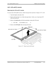
...and make it flat. 2. Remove the keyboard cover while releasing latches. (In the case of removing LCD before the keyboard) 3. Mask seal M2.5×6B FLAT HEAD M2.5×6B FLAT HEAD LCD mask Figure 4-37 Removing the LCD mask TECRA A8 /Satellite Pro A120 Maintenance Manual (960-...573) [CONFIDENTIAL] 4-57 Remove the mask seals and following screws securing the LCD mask. • M2.5×6B FLAT HEAD screw ×2 4. 4.25 LCD unit/FL inverter 4 Replacement Procedures 4 Replacement Procedures 4.25 LCD unit...
...and make it flat. 2. Remove the keyboard cover while releasing latches. (In the case of removing LCD before the keyboard) 3. Mask seal M2.5×6B FLAT HEAD M2.5×6B FLAT HEAD LCD mask Figure 4-37 Removing the LCD mask TECRA A8 /Satellite Pro A120 Maintenance Manual (960-...573) [CONFIDENTIAL] 4-57 Remove the mask seals and following screws securing the LCD mask. • M2.5×6B FLAT HEAD screw ×2 4. 4.25 LCD unit/FL inverter 4 Replacement Procedures 4 Replacement Procedures 4.25 LCD unit...
Maintenance Manual
Page 307
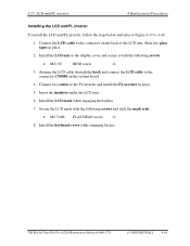
...glass tapes in place. 5. Install the LCD unit to 4-40. 1. TECRA A8 /Satellite Pro A120 Maintenance Manual (960-573) [CONFIDENTIAL] 4-61 Insert the insulator under the LCD unit. 6. 4.25 LCD unit/FL inverter 4 Replacement Procedures Installing the LCD unit/FL inverter To install the LCD unit/FL ...215;6B FLAT HEAD screw ×2 8. Connect two cables to the connector CN5000 on the back of the LCD unit. Install the keyboard cover while engaging latches. Install the LCD mask while engaging the latches. 7. Arrange the LCD cable through the hook and connect the LCD...
...glass tapes in place. 5. Install the LCD unit to 4-40. 1. TECRA A8 /Satellite Pro A120 Maintenance Manual (960-573) [CONFIDENTIAL] 4-61 Insert the insulator under the LCD unit. 6. 4.25 LCD unit/FL inverter 4 Replacement Procedures Installing the LCD unit/FL inverter To install the LCD unit/FL ...215;6B FLAT HEAD screw ×2 8. Connect two cables to the connector CN5000 on the back of the LCD unit. Install the keyboard cover while engaging latches. Install the LCD mask while engaging the latches. 7. Arrange the LCD cable through the hook and connect the LCD...


