Installation Instructions
Page 2
...Blower Motor Installation 11 Remote Installation (optional 15 VCIN Model Installation 18 VCIB Model Installation 26 Installing Filters, Filter Spacers, & Grease Trays 28 Service 29 Before Calling Service 29 Product Data Rating Plate 29 Installer Checklist 29 To Clean & Protect Exterior Surfaces 30 THERMADOR...® Service, Parts & Accessories back page This THERMADOR® appliance is made by BSH Home Appliances Corporation 1901 Main Street, Suite 600 Irvine, CA...
...Blower Motor Installation 11 Remote Installation (optional 15 VCIN Model Installation 18 VCIB Model Installation 26 Installing Filters, Filter Spacers, & Grease Trays 28 Service 29 Before Calling Service 29 Product Data Rating Plate 29 Installer Checklist 29 To Clean & Protect Exterior Surfaces 30 THERMADOR...® Service, Parts & Accessories back page This THERMADOR® appliance is made by BSH Home Appliances Corporation 1901 Main Street, Suite 600 Irvine, CA...
Installation Instructions
Page 5
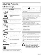
... models only) 2 or 4 - Lock service panel to play with backdraft damper 2, 3, or 4 - Halogen lights (installed) 1 - Remote blower adaptor 1 - Fastener assortment CAUTION: Before installing, turn power OFF at the service panel. Never allow children to prevent power from being turned ON ...accidentally. Remote Control Remove all THERMADOR® appliance packaging material is recyclable. Stainless steel baffle filters (depending on model size) 1 - Please, recycle the packaging...
... models only) 2 or 4 - Lock service panel to play with backdraft damper 2, 3, or 4 - Halogen lights (installed) 1 - Remote blower adaptor 1 - Fastener assortment CAUTION: Before installing, turn power OFF at the service panel. Never allow children to prevent power from being turned ON ...accidentally. Remote Control Remove all THERMADOR® appliance packaging material is recyclable. Stainless steel baffle filters (depending on model size) 1 - Please, recycle the packaging...
Installation Instructions
Page 7
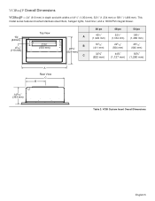
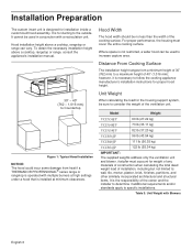
... mm), 52½" (1,334 mm) or 58½" (1,486 mm). This model series features brushed stainless-steel filters, halogen lights, hood liner, and a 1000CFM integral blower. 15/8" (42mm) 45/16" (110 mm) Top View 21¾" (553 mm) A B 24¾" (629 mm) C 36 po 40½" (1,029 mm) 163/16" (411...
... mm), 52½" (1,334 mm) or 58½" (1,486 mm). This model series features brushed stainless-steel filters, halogen lights, hood liner, and a 1000CFM integral blower. 15/8" (42mm) 45/16" (110 mm) Top View 21¾" (553 mm) A B 24¾" (629 mm) C 36 po 40½" (1,029 mm) 163/16" (411...
Installation Instructions
Page 8
...the width of 40" (1,016 mm); Installer must cover the entire cooking surface. Table 3: Unit Weight with Blowers English 6 Model Weight VCIN36JP 60 lb (27.22 kg) VCIN48JP 73 lb (33.11 kg) VCIN54JP 82 lb (37.20 kg) VCIB36JP 96 lb (43.54 kg)...weights address only the ventilation unit and blower. however, it is necessary to follow the cooking appliance manufacturer's installation instructions for installation inside a custom-built hood assembly. Distance From Cooking Surface The installation height ranges from heat if a THERMADOR PROFESSIONAL® series range or rangetop ...
...the width of 40" (1,016 mm); Installer must cover the entire cooking surface. Table 3: Unit Weight with Blowers English 6 Model Weight VCIN36JP 60 lb (27.22 kg) VCIN48JP 73 lb (33.11 kg) VCIN54JP 82 lb (37.20 kg) VCIB36JP 96 lb (43.54 kg)...weights address only the ventilation unit and blower. however, it is necessary to follow the cooking appliance manufacturer's installation instructions for installation inside a custom-built hood assembly. Distance From Cooking Surface The installation height ranges from heat if a THERMADOR PROFESSIONAL® series range or rangetop ...
Installation Instructions
Page 9
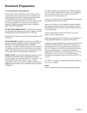
... proper ducting. It is required for other sizes. Always use of make -up air systems when using a 10" (254 mm) duct, THERMADOR® recommends not exceeding 150 ft (46 m) of a remote blower gives the best delivery. The damper should have 30 ft (9.2 m) of straight 10" (254 mm) duct with a minimum diameter of...
... proper ducting. It is required for other sizes. Always use of make -up air systems when using a 10" (254 mm) duct, THERMADOR® recommends not exceeding 150 ft (46 m) of a remote blower gives the best delivery. The damper should have 30 ft (9.2 m) of straight 10" (254 mm) duct with a minimum diameter of...

Installation Instructions
Page 12
... An exterior installation may be more powerful blower. Electrical Requirements The unit requires a 120V AC, 60Hz. 15A branch circuit. B149.1 and .2 - This appliance has a cord with THERMADOR ventilation hoods. Blower selection will vary based on page 7). ...Check your local building codes for use a straight run . Installation Codes for recommended blowers. The plug must be grounded. Integral Blowers These blowers are mounted along the ...
... An exterior installation may be more powerful blower. Electrical Requirements The unit requires a 120V AC, 60Hz. 15A branch circuit. B149.1 and .2 - This appliance has a cord with THERMADOR ventilation hoods. Blower selection will vary based on page 7). ...Check your local building codes for use a straight run . Installation Codes for recommended blowers. The plug must be grounded. Integral Blowers These blowers are mounted along the ...
Installation Instructions
Page 13
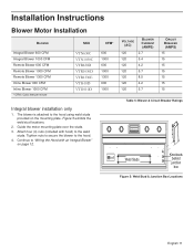
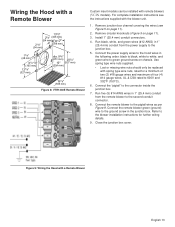
... 120 5.4 120 4.2 120 5.7 120 8.5 120 4.2 120 5.7 CIRCUIT BREAKER (AMPS) 15 15 15 15 15 15 15 Table 5: Blower & Circuit Breaker Ratings x4 Weld Studs Knockouts behind junction box Figure 5: Weld Stud & Junction Box Locations English 11 Figure 5 exhibits the...Wiring the Hood with hood) to the hood. 4. Installation Instructions Blower Motor Installation BLOWER Integral Blower 600 CFM Integral Blower 1000 CFM Remote Blower 600 CFM Remote Blower 1000 CFM Remote Blower 1300 CFM Inline Blower 600 CFM Inline Blower 1000 CFM * CFM= Cubic feet per minute SKU VTN630C VTN1030C ...
... 120 5.4 120 4.2 120 5.7 120 8.5 120 4.2 120 5.7 CIRCUIT BREAKER (AMPS) 15 15 15 15 15 15 15 Table 5: Blower & Circuit Breaker Ratings x4 Weld Studs Knockouts behind junction box Figure 5: Weld Stud & Junction Box Locations English 11 Figure 5 exhibits the...Wiring the Hood with hood) to the hood. 4. Installation Instructions Blower Motor Installation BLOWER Integral Blower 600 CFM Integral Blower 1000 CFM Remote Blower 600 CFM Remote Blower 1000 CFM Remote Blower 1300 CFM Inline Blower 600 CFM Inline Blower 1000 CFM * CFM= Cubic feet per minute SKU VTN630C VTN1030C ...
Installation Instructions
Page 14
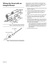
...mm) 41/8" (105 mm) 21/4" (57 mm) 63/4" 67/8" (171 mm) (175 mm) 25" (635 mm) Figure 6: Integral Blower Model VTN1030C From Blower Integral Blower models VTN630C and VTN1030C are integrated into the hood at the time of four (4) #14 gauge wires, UL & CSA rated to green ground screw... the Hood with spring type wire nuts rated for a minimum of two (2) #18 gauge wires and maximum of installation (VCIN models). Connect the blower's Molex plug connector to the junction box. 6. For complete installation instructions see Figure 5 on chassis. Remove circular knockouts (Figure 5 on page 11...
...mm) 41/8" (105 mm) 21/4" (57 mm) 63/4" 67/8" (171 mm) (175 mm) 25" (635 mm) Figure 6: Integral Blower Model VTN1030C From Blower Integral Blower models VTN630C and VTN1030C are integrated into the hood at the time of four (4) #14 gauge wires, UL & CSA rated to green ground screw... the Hood with spring type wire nuts rated for a minimum of two (2) #18 gauge wires and maximum of installation (VCIN models). Connect the blower's Molex plug connector to the junction box. 6. For complete installation instructions see Figure 5 on chassis. Remove circular knockouts (Figure 5 on page 11...
Installation Instructions
Page 15
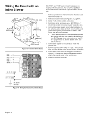
...to green ground screw on page 11). 2. Use spring type wire nuts supplied. • Lost or missing wire nuts should only be installed with the blower unit. 1. Run five (5) #14 AWG wires in the following order: black to black, white to white, and green wire to the junction box...(327 mm) dia. 97/8" (251 mm) 203/4" 10" (527 mm) (254 mm) 19 7/8" (505 mm) Figure 8: VTR1330E Remote Blower Custom insert models can be replaced with a Remote Blower English 13 Run black, white, and green wires (#12 AWG) in the junction box. For complete installation instructions see Figure 5 on...
...to green ground screw on page 11). 2. Use spring type wire nuts supplied. • Lost or missing wire nuts should only be installed with the blower unit. 1. Run five (5) #14 AWG wires in the following order: black to black, white to white, and green wire to the junction box...(327 mm) dia. 97/8" (251 mm) 203/4" 10" (527 mm) (254 mm) 19 7/8" (505 mm) Figure 8: VTR1330E Remote Blower Custom insert models can be replaced with a Remote Blower English 13 Run black, white, and green wires (#12 AWG) in the junction box. For complete installation instructions see Figure 5 on...
Installation Instructions
Page 16
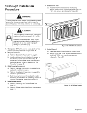
... (22 mm) ø 9 7/8" (251 mm) 19 1/8" (486 mm) 13/4" (44 mm) 12 7/8" (327 mm) 14 3/8" (365 mm) Figure 10: VTI1010D Inline Blower 1. Remove junction box channel covering the wires (see the instructions supplied with spring type wire nuts, rated for a minimum of two (2 #18 gauge wires and...to 600V and 302°F (150°C). 6. Connect the "pigtail" to green ground screw on chassis. Figure 11: Wiring the Hood with inline blowers. Install 1" (25.4 mm) conduit connectors. 4. Close the junction box cover. Connect the power supply wires to the hood wires in the junction box...
... (22 mm) ø 9 7/8" (251 mm) 19 1/8" (486 mm) 13/4" (44 mm) 12 7/8" (327 mm) 14 3/8" (365 mm) Figure 10: VTI1010D Inline Blower 1. Remove junction box channel covering the wires (see the instructions supplied with spring type wire nuts, rated for a minimum of two (2 #18 gauge wires and...to 600V and 302°F (150°C). 6. Connect the "pigtail" to green ground screw on chassis. Figure 11: Wiring the Hood with inline blowers. Install 1" (25.4 mm) conduit connectors. 4. Close the junction box cover. Connect the power supply wires to the hood wires in the junction box...
Installation Instructions
Page 23
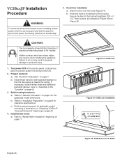
...at least two people to prevent power from being turned ON. 2. Lock service panel to lift it requires at the service panel. Install blower motor a) Refer to the hood with backdraft damper so that the flap opens up toward the ceiling. Secure the trim to "Choosing the Correct... the service panel and lock the panel to do so may have sharp edges. If necessary, install thermal break and additional backdraft damper (refer to "Blower Motor Installation" beginning on accidentally. ½" (12.7 mm) x18 CAUTION: The hood weighs at least 60 lbs; Hidden surfaces may result in Figure 26. ...
...at least two people to prevent power from being turned ON. 2. Lock service panel to lift it requires at the service panel. Install blower motor a) Refer to the hood with backdraft damper so that the flap opens up toward the ceiling. Secure the trim to "Choosing the Correct... the service panel and lock the panel to do so may have sharp edges. If necessary, install thermal break and additional backdraft damper (refer to "Blower Motor Installation" beginning on accidentally. ½" (12.7 mm) x18 CAUTION: The hood weighs at least 60 lbs; Hidden surfaces may result in Figure 26. ...
Installation Instructions
Page 24
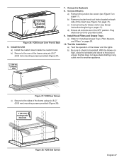
... side Figure 27: VCIN Side Screws 7. b) Be sure to check for another appliance. b) Remove circular knock-out holes located on back side of the blower and the lights. English 22 d) Ensure all controls are in Figure 27. 2" (50.8 mm) mounting screws X3 per side as indicated in the OFF... position. c) Connect wiring for applicable blower motor (see Figure 5 on page 11). Test the installation a) Test the operation of the insert (see blower instructions beginning on page 11). With the blower on high, close the windows and doors to the area to ductwork 8....
... side Figure 27: VCIN Side Screws 7. b) Be sure to check for another appliance. b) Remove circular knock-out holes located on back side of the blower and the lights. English 22 d) Ensure all controls are in Figure 27. 2" (50.8 mm) mounting screws X3 per side as indicated in the OFF... position. c) Connect wiring for applicable blower motor (see Figure 5 on page 11). Test the installation a) Test the operation of the insert (see blower instructions beginning on page 11). With the blower on high, close the windows and doors to the area to ductwork 8....
Installation Instructions
Page 28
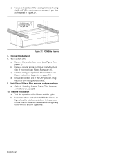
... switched on accidentally. 5. Prepare ductwork a) See "Ductwork Preparation" on page 23. 4. c) Build housing framework for applicable model according to "Blower Motor Installation" beginning on page 6 for the applicable model dimensions. Install blower motor a) Refer to dimensions in property damage or personal injury. 1. CAUTION: The hood weighs at the service panel. b) Install metal...
... switched on accidentally. 5. Prepare ductwork a) See "Ductwork Preparation" on page 23. 4. c) Build housing framework for applicable model according to "Blower Motor Installation" beginning on page 6 for the applicable model dimensions. Install blower motor a) Refer to dimensions in property damage or personal injury. 1. CAUTION: The hood weighs at the service panel. b) Install metal...
Installation Instructions
Page 29
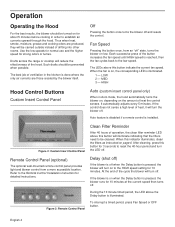
... controls are in any outlet vent for another appliance. 2" (50.8 mm) X6 mounting screws Figure 37: VCIB Rear Screws c) Secure to the sides of the blower and the lights. ½" (12.7 mm) X6 each front & back side Figure 36: VCIB Secure Liner Front & Back 6. b) Secure to "Installing Grease ...). 2" (50.8 mm) mounting screws X3 per side Figure 38: VCIB Side Screws English 27 c) Connect wiring for backdraft. Connect to check for blower motor (see blower instructions beginning on high, close the windows and doors to the area to ensure that fan does not cause back drafting in the OFF...
... controls are in any outlet vent for another appliance. 2" (50.8 mm) X6 mounting screws Figure 37: VCIB Rear Screws c) Secure to the sides of the blower and the lights. ½" (12.7 mm) X6 each front & back side Figure 36: VCIB Secure Liner Front & Back 6. b) Secure to "Installing Grease ...). 2" (50.8 mm) mounting screws X3 per side Figure 38: VCIB Side Screws English 27 c) Connect wiring for backdraft. Connect to check for blower motor (see blower instructions beginning on high, close the windows and doors to the area to ensure that fan does not cause back drafting in the OFF...
User Manual
Page 6
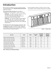
...halogen lights, hood liner, and a 1000CFM integral blower. All VCINxxJP hoods require the choice of 41½" (1,054 mm), 52½" (1,334 mm) or 58½" (1,486 mm). see the Installation Manual for two styles of THERMADOR PROFESSIONAL® custom insert hoods: • ...VCINxxJP - 22" (559 mm) in depth, and with THERMADOR ventilation hoods. This manual provides information for more details. Use only THERMADOR® blowers with widths of a remote, inline, or integral blower. This model series features brushed stainless-steel filters and halogen lights. • ...
...halogen lights, hood liner, and a 1000CFM integral blower. All VCINxxJP hoods require the choice of 41½" (1,054 mm), 52½" (1,334 mm) or 58½" (1,486 mm). see the Installation Manual for two styles of THERMADOR PROFESSIONAL® custom insert hoods: • ...VCINxxJP - 22" (559 mm) in depth, and with THERMADOR ventilation hoods. This manual provides information for more details. Use only THERMADOR® blowers with widths of a remote, inline, or integral blower. This model series features brushed stainless-steel filters and halogen lights. • ...
User Manual
Page 9
...above the Delay button is reached, then the fan cycles back to be cleaned. English 4 Off Pressing the button once turns the blower off " state, turns the blower on , the corresponding LED is on low. It automatically adjusts every 5 minutes. When this button for 3 seconds to reset ...clean filter reminder LED above this button will turn the LED off . Auto feature is disabled if a remote control is pressed, the blower will illuminate indicating that the filters need to the low speed. Such drafts should be turned on to the Remote Control Installation Instruction for ...
...above the Delay button is reached, then the fan cycles back to be cleaned. English 4 Off Pressing the button once turns the blower off " state, turns the blower on , the corresponding LED is on low. It automatically adjusts every 5 minutes. When this button for 3 seconds to reset ...clean filter reminder LED above this button will turn the LED off . Auto feature is disabled if a remote control is pressed, the blower will illuminate indicating that the filters need to the low speed. Such drafts should be turned on to the Remote Control Installation Instruction for ...

User Manual
Page 10
...panel only) Heat sensor feature is disabled if a remote control is not working due to a damaged sensor. When activated, the blower will turn on . During reset, the control will blink, indicating an overtemperature condition. High Temperature Fault Condition The circuit is equipped .... Lights This button controls the halogen lighting. Light controls will be changed or turned off . 1 - English 5 If the blower is set to the high temperature condition. Over-temperature Condition The high temperature sensor protects the hood from high temperatures which may damage...
...panel only) Heat sensor feature is disabled if a remote control is not working due to a damaged sensor. When activated, the blower will turn on . During reset, the control will blink, indicating an overtemperature condition. High Temperature Fault Condition The circuit is equipped .... Lights This button controls the halogen lighting. Light controls will be changed or turned off . 1 - English 5 If the blower is set to the high temperature condition. Over-temperature Condition The high temperature sensor protects the hood from high temperatures which may damage...
User Manual
Page 12
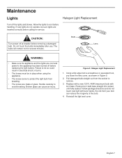
... electrical shock or burns. • The lenses must be sure lights are cool and power to avoid breaking. CAUTION: Turn power off the lights and blower. Bulb Lens WARNING: • Make sure the appliance and the lights are inserted correctly before calling for several minutes.
... electrical shock or burns. • The lenses must be sure lights are cool and power to avoid breaking. CAUTION: Turn power off the lights and blower. Bulb Lens WARNING: • Make sure the appliance and the lights are inserted correctly before calling for several minutes.
User Manual
Page 13
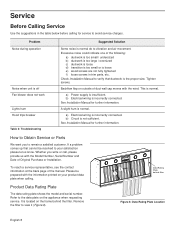
... 8 Refer to your product data plate when calling. Remove the filter to remain a satisfied customer. Problem Noise during operation Noise when unit is off Fan blower does not work Lights hum Hood trips breaker Table 2: Troubleshooting Suggested Solution Some noise is incorrectly connected. Tighten screws. Excessive noise could indicate one of...
... 8 Refer to your product data plate when calling. Remove the filter to remain a satisfied customer. Problem Noise during operation Noise when unit is off Fan blower does not work Lights hum Hood trips breaker Table 2: Troubleshooting Suggested Solution Some noise is incorrectly connected. Tighten screws. Excessive noise could indicate one of...


