Installation Instructions
Page 9
...permissible lengths for duct runs to specific installations. Keep duct runs as short and straight as possible to locale. Hoods are supplied with a minimum diameter of 6" (150 mm). For example, assume you would add 12 ft ... may require the use of make -up air systems when using a 10" (254 mm) duct, THERMADOR® recommends not exceeding 150 ft (46 m) of the thermal break. Back to specific installations. A... to outdoors. Use Table 4 on the cold air side of duct. The damper should vent directly outdoors (not into an attic, underneath the house, into the garage or into any...
...permissible lengths for duct runs to specific installations. Keep duct runs as short and straight as possible to locale. Hoods are supplied with a minimum diameter of 6" (150 mm). For example, assume you would add 12 ft ... may require the use of make -up air systems when using a 10" (254 mm) duct, THERMADOR® recommends not exceeding 150 ft (46 m) of the thermal break. Back to specific installations. A... to outdoors. Use Table 4 on the cold air side of duct. The damper should vent directly outdoors (not into an attic, underneath the house, into the garage or into any...
Installation Instructions
Page 24
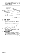
... sure to ductwork 8. English 22 Connect to check for backdraft. c) Connect wiring for another appliance. Install hood filters, filter spacers, and grease trays a) Refer to ensure that fan does not cause back drafting in any outlet vent for applicable blower motor (see Figure 5 on page 28. 10. Connect electric a) Remove the junction...
... sure to ductwork 8. English 22 Connect to check for backdraft. c) Connect wiring for another appliance. Install hood filters, filter spacers, and grease trays a) Refer to ensure that fan does not cause back drafting in any outlet vent for applicable blower motor (see Figure 5 on page 28. 10. Connect electric a) Remove the junction...
Installation Instructions
Page 29
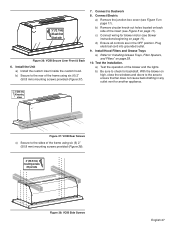
...b) Be sure to "Installing Grease Trays, Filter Spacers, and Filters" on page 11). Install the Unit a) Install the custom insert inside the custom hood. Plug electrical cord into grounded outlet. 9. b) Secure to the rear of the insert (see Figure 5 on page 28. 10. b) Remove circular ...-out holes located on page 11). d) Ensure all controls are in any outlet vent for another appliance. 2" (50.8 mm) X6 mounting screws Figure 37: VCIB Rear Screws c) Secure to Ductwork 8. Test the installation. Install Hood Filters and Grease Trays a) Refer to check for blower motor (see Figure 5 ...
...b) Be sure to "Installing Grease Trays, Filter Spacers, and Filters" on page 11). Install the Unit a) Install the custom insert inside the custom hood. Plug electrical cord into grounded outlet. 9. b) Secure to the rear of the insert (see Figure 5 on page 28. 10. b) Remove circular ...-out holes located on page 11). d) Ensure all controls are in any outlet vent for another appliance. 2" (50.8 mm) X6 mounting screws Figure 37: VCIB Rear Screws c) Secure to Ductwork 8. Test the installation. Install Hood Filters and Grease Trays a) Refer to check for blower motor (see Figure 5 ...


