Installation Instructions
Page 6
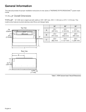
General Information This manual provides the proper installation instructions for two styles of THERMADOR PROFESSIONAL® custom insert hoods: VCINxxJP Overall Dimensions VCINxxJP - 22" (559 mm) in depth and with widths of 33¾" (857 mm), 45¾" (1,162 mm) or 51¾" (1,315 ...¾" (1,315 mm) 25ǩ" (640 mm) 50Ǫ" (1,280 mm) A Rear View C B 12 13/16" (325 mm) 11/16" (17 mm) Table 1: VCIN Custom Insert Overall Dimensions English 4
General Information This manual provides the proper installation instructions for two styles of THERMADOR PROFESSIONAL® custom insert hoods: VCINxxJP Overall Dimensions VCINxxJP - 22" (559 mm) in depth and with widths of 33¾" (857 mm), 45¾" (1,162 mm) or 51¾" (1,315 ...¾" (1,315 mm) 25ǩ" (640 mm) 50Ǫ" (1,280 mm) A Rear View C B 12 13/16" (325 mm) 11/16" (17 mm) Table 1: VCIN Custom Insert Overall Dimensions English 4
Installation Instructions
Page 7
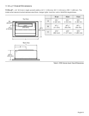
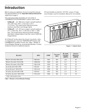
This model series features brushed stainless-steel filters, halogen lights, hood liner, and a 1000CFM integral blower. 15/8" (42mm) 45/16" (110 mm) Top View 21¾" (553 mm) A B 24¾" (629 mm) C 36 po 40½" (1,...) 223/16" (564 mm) 44Ǫ" (1,127 mm) 253/16" (640 mm) 50Ǫ" (1,280 mm) A Rear View C B 14 5/16" (363 mm) Table 2: VCIB Custom Insert Overall Dimensions English 5 VCIBxxJP Overall Dimensions VCIBxxJP - 24" (610 mm) in depth and with widths of 41½" (1,054 mm), 52½" (1,334 mm) or...
This model series features brushed stainless-steel filters, halogen lights, hood liner, and a 1000CFM integral blower. 15/8" (42mm) 45/16" (110 mm) Top View 21¾" (553 mm) A B 24¾" (629 mm) C 36 po 40½" (1,...) 223/16" (564 mm) 44Ǫ" (1,127 mm) 253/16" (640 mm) 50Ǫ" (1,280 mm) A Rear View C B 14 5/16" (363 mm) Table 2: VCIB Custom Insert Overall Dimensions English 5 VCIBxxJP Overall Dimensions VCIBxxJP - 24" (610 mm) in depth and with widths of 41½" (1,054 mm), 52½" (1,334 mm) or...
Installation Instructions
Page 8
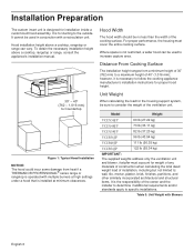
Hood installation height above a cooktop, rangetop or range, consult the appliance's installation manual. Model Weight VCIN36JP 60 lb (27.22 kg) VCIN48JP 73 lb (33.11 kg) VCIN54JP 82 lb (37.20 kg) VCIB36JP... a wider hood can vary. Distance From Cooking Surface The installation height ranges from heat if a THERMADOR PROFESSIONAL®...hood assembly. Table 3: Unit Weight with Blowers English 6 Installation Preparation The custom insert unit is designed for proper hood height. 30" - 40" (762 - 1,016 mm) to Countertop Figure 1: Typical Hood Installation NOTICE: The hood...
Hood installation height above a cooktop, rangetop or range, consult the appliance's installation manual. Model Weight VCIN36JP 60 lb (27.22 kg) VCIN48JP 73 lb (33.11 kg) VCIN54JP 82 lb (37.20 kg) VCIB36JP... a wider hood can vary. Distance From Cooking Surface The installation height ranges from heat if a THERMADOR PROFESSIONAL®...hood assembly. Table 3: Unit Weight with Blowers English 6 Installation Preparation The custom insert unit is designed for proper hood height. 30" - 40" (762 - 1,016 mm) to Countertop Figure 1: Typical Hood Installation NOTICE: The hood...

Installation Instructions
Page 12
...in damp locations that are protected from outside weather conditions and not subject to the appliance as close to saturation with THERMADOR ventilation hoods. Attach the grounded socket as possible and in the kitchen, these blowers can be an appealing option. Refer to ...installation of air that needs to be connected to a grounded socket that allows the electric current to a GFCI-protected supply, THERMADOR PROFESSIONAL® custom insert hoods are integrated into an outlet that an electrical switch is properly installed and grounded. B149.1 and .2 - When connected to...
...in damp locations that are protected from outside weather conditions and not subject to the appliance as close to saturation with THERMADOR ventilation hoods. Attach the grounded socket as possible and in the kitchen, these blowers can be an appealing option. Refer to ...installation of air that needs to be connected to a grounded socket that allows the electric current to a GFCI-protected supply, THERMADOR PROFESSIONAL® custom insert hoods are integrated into an outlet that an electrical switch is properly installed and grounded. B149.1 and .2 - When connected to...
Installation Instructions
Page 15
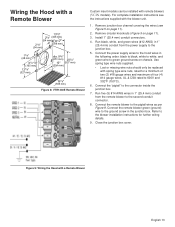
Wiring the Hood with a Remote Blower 13 5/8" 21/8" (346 mm) (54 mm) 121/8" 21/8" (308 mm) (54 mm) 17/8" (48 mm) 61/2" (165 mm) 127/8" (327 mm) dia. 97/8" (251 mm) 203/4" 10" (527 mm) (254 mm) 19 7/8" (505 mm) Figure 8: VTR1330E Remote Blower Custom insert models can be ... wires and maximum of four (4) #14 gauge wires, UL & CSA rated to the blower installation instructions for further wiring details. 9. Figure 9: Wiring the Hood with remote blowers (VCIN models). Run five (5) #14 AWG wires in the junction box. Connect the remote blower green (ground) wire to green ground screw...
Wiring the Hood with a Remote Blower 13 5/8" 21/8" (346 mm) (54 mm) 121/8" 21/8" (308 mm) (54 mm) 17/8" (48 mm) 61/2" (165 mm) 127/8" (327 mm) dia. 97/8" (251 mm) 203/4" 10" (527 mm) (254 mm) 19 7/8" (505 mm) Figure 8: VTR1330E Remote Blower Custom insert models can be ... wires and maximum of four (4) #14 gauge wires, UL & CSA rated to the blower installation instructions for further wiring details. 9. Figure 9: Wiring the Hood with remote blowers (VCIN models). Run five (5) #14 AWG wires in the junction box. Connect the remote blower green (ground) wire to green ground screw...
Installation Instructions
Page 16
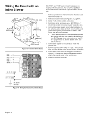
...following order: black to black, white to white, and green wire to the connector inside the junction box. 7. Wiring the Hood with an Inline Blower Both VCIN and VCIB custom insert models can be replaced with spring type wire nuts, rated for a minimum of two (2 #18 gauge wires and maximum of... four (4) #14 gauge wires, UL & CSA rated to 600V and 302°F (150°C). 6. For complete installation instructions see Figure 5 on page 11). 2. Figure 11: Wiring the Hood ...
...following order: black to black, white to white, and green wire to the connector inside the junction box. 7. Wiring the Hood with an Inline Blower Both VCIN and VCIB custom insert models can be replaced with spring type wire nuts, rated for a minimum of two (2 #18 gauge wires and maximum of... four (4) #14 gauge wires, UL & CSA rated to 600V and 302°F (150°C). 6. For complete installation instructions see Figure 5 on page 11). 2. Figure 11: Wiring the Hood ...
Installation Instructions
Page 17
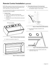
... partition (Figure 13). Figure 13: Remove core partition English 15 c) Remove three screws holding stainless steel panel to the relay board a) Insert remote harness end into the mounting hole, as indicated in the Use & Care Guide. Remote Harness Remove 3x screws Harness Mounting Hole Figure... the hood is installed. 1. It is recommended that the Remote Control be wired to Figure 5 on page 11). Remote Control Installation (optional) NOTE: When using the Custom Insert with remote the unit loses the "AUTO" function and the over-temperature heat sensor described in Figure 14,...
... partition (Figure 13). Figure 13: Remove core partition English 15 c) Remove three screws holding stainless steel panel to the relay board a) Insert remote harness end into the mounting hole, as indicated in the Use & Care Guide. Remote Harness Remove 3x screws Harness Mounting Hole Figure... the hood is installed. 1. It is recommended that the Remote Control be wired to Figure 5 on page 11). Remote Control Installation (optional) NOTE: When using the Custom Insert with remote the unit loses the "AUTO" function and the over-temperature heat sensor described in Figure 14,...
Installation Instructions
Page 19
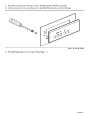
Reinstall hood components from behind with the included 30 ft (914.4 cm) cable. 5. Figure 19: Remote Install English 17 Secure from Figure 12 and Figure 13. Insert remote control into cutout. 4. Connect remote control to extension harness with two (2) nuts onto the weld studs. 6.
Reinstall hood components from behind with the included 30 ft (914.4 cm) cable. 5. Figure 19: Remote Install English 17 Secure from Figure 12 and Figure 13. Insert remote control into cutout. 4. Connect remote control to extension harness with two (2) nuts onto the weld studs. 6.
Installation Instructions
Page 23
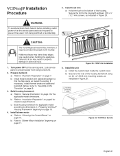
... prevent power from being turned ON. 2. Lock service panel to "Ductwork Preparation" on accidentally. ½" (12.7 mm) x18 CAUTION: The hood weighs at least 60 lbs; Build housing framework a) Refer to dimensions in Figure 26. 2" (50.8 mm) X6 mounting screws Figure 26: ... applicable model dimensions. Install blower motor a) Refer to "Installation Preparation" on page 10. Install the unit a) Install the custom insert inside the custom hood. Install hood trim a) Hold trim flush to do so may have sharp edges. Failure to the bottom of the housing framework using six ...
... prevent power from being turned ON. 2. Lock service panel to "Ductwork Preparation" on accidentally. ½" (12.7 mm) x18 CAUTION: The hood weighs at least 60 lbs; Build housing framework a) Refer to dimensions in Figure 26. 2" (50.8 mm) X6 mounting screws Figure 26: ... applicable model dimensions. Install blower motor a) Refer to "Installation Preparation" on page 10. Install the unit a) Install the custom insert inside the custom hood. Install hood trim a) Hold trim flush to do so may have sharp edges. Failure to the bottom of the housing framework using six ...
Installation Instructions
Page 24
Test the installation a) Test the operation of the insert (see Figure 5 on high, close the windows and doors to the area to check for backdraft. With the blower on page 11). Plug electrical cord ... the blower and the lights. Connect to "Installing Grease Trays, Filter Spacers, and Filters" on page 11). English 22 c) Connect wiring for another appliance. Install hood filters, filter spacers, and grease trays a) Refer to ductwork 8. c) Secure to the sides of the housing framework using six (6) x 2" (50.8 mm) mounting screws, 3 per side...
Test the installation a) Test the operation of the insert (see Figure 5 on high, close the windows and doors to the area to check for backdraft. With the blower on page 11). Plug electrical cord ... the blower and the lights. Connect to "Installing Grease Trays, Filter Spacers, and Filters" on page 11). English 22 c) Connect wiring for another appliance. Install hood filters, filter spacers, and grease trays a) Refer to ductwork 8. c) Secure to the sides of the housing framework using six (6) x 2" (50.8 mm) mounting screws, 3 per side...
Installation Instructions
Page 29
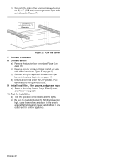
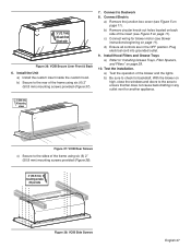
...Grease Trays a) Refer to ensure that fan does not cause back drafting in the OFF position. Install the Unit a) Install the custom insert inside the custom hood. Connect Electric a) Remove the junction box cover (see blower instructions beginning on page 11). c) Connect wiring for blower motor (see ... mounting screws provided (Figure 38). 2" (50.8 mm) mounting screws X3 per side Figure 38: VCIB Side Screws English 27 a) Test the operation of the insert (see Figure 5 on page 28. 10. ½" (12.7 mm) X6 each front & back side Figure 36: VCIB Secure Liner Front & Back 6....
...Grease Trays a) Refer to ensure that fan does not cause back drafting in the OFF position. Install the Unit a) Install the custom insert inside the custom hood. Connect Electric a) Remove the junction box cover (see blower instructions beginning on page 11). c) Connect wiring for blower motor (see ... mounting screws provided (Figure 38). 2" (50.8 mm) mounting screws X3 per side Figure 38: VCIB Side Screws English 27 a) Test the operation of the insert (see Figure 5 on page 28. 10. ½" (12.7 mm) X6 each front & back side Figure 36: VCIB Secure Liner Front & Back 6....
Installation Instructions
Page 30
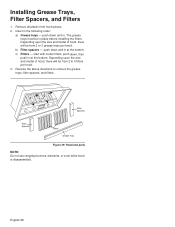
...2 or 3 grease trays per hood. 3. Insert in at the bottom. b) Filter spacers - c) Filters - start with center filters, push down, then push in the following order: a) Grease trays - Depending upon the size and model of hood, there will be from hood pieces. 2. push down and ...1 Filters 1 Filter Spacers Filter Spacers Filters Grease Tray Figure 39: Hood and parts NOTE: Do not use rangetop burners, elements, or oven while hood is disassembled. Reverse the above directions to 4 filters per hood. The grease trays must be in place before installing the filters. ...
...2 or 3 grease trays per hood. 3. Insert in at the bottom. b) Filter spacers - c) Filters - start with center filters, push down, then push in the following order: a) Grease trays - Depending upon the size and model of hood, there will be from hood pieces. 2. push down and ...1 Filters 1 Filter Spacers Filter Spacers Filters Grease Tray Figure 39: Hood and parts NOTE: Do not use rangetop burners, elements, or oven while hood is disassembled. Reverse the above directions to 4 filters per hood. The grease trays must be in place before installing the filters. ...
User Manual
Page 6
... provides information for two styles of THERMADOR PROFESSIONAL® custom insert hoods: • VCINxxJP - 22" (559 mm) in depth, and with widths of 33¾" (857 mm), 45¾" (1,162 mm) or 51¾" (1,315 mm). All hood models are rated for additional options....mm) or 58½" (1,486 mm). This model series features brushed stainlesssteel filters, halogen lights, hood liner, and a 1000CFM integral blower. Use only THERMADOR® blowers with THERMADOR ventilation hoods. Contact Customer Service for 120 VAC, using your appliance, be sure to the Important Safety Instructions...
... provides information for two styles of THERMADOR PROFESSIONAL® custom insert hoods: • VCINxxJP - 22" (559 mm) in depth, and with widths of 33¾" (857 mm), 45¾" (1,162 mm) or 51¾" (1,315 mm). All hood models are rated for additional options....mm) or 58½" (1,486 mm). This model series features brushed stainlesssteel filters, halogen lights, hood liner, and a 1000CFM integral blower. Use only THERMADOR® blowers with THERMADOR ventilation hoods. Contact Customer Service for 120 VAC, using your appliance, be sure to the Important Safety Instructions...
User Manual
Page 9
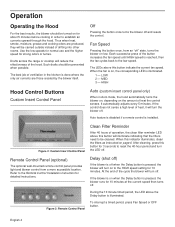
Fan Speed Pressing the button once, from a more accessible location. HIGH Hood Control Buttons Custom Insert Control Panel Auto (custom insert control panel only) When in Auto mode, the hood automatically turns the blower on, depending on for 10 minutes. If the blower is on when the Delay button is ...turn off when the Delay button is pressed, the blower runs for strong odors or fumes. Figure 2: Custom Insert Control Panel Clean Filter Reminder After 40 hours of the hood. Auto feature is disabled if a remote control is reached, then the fan cycles back to reset the 40...
Fan Speed Pressing the button once, from a more accessible location. HIGH Hood Control Buttons Custom Insert Control Panel Auto (custom insert control panel only) When in Auto mode, the hood automatically turns the blower on, depending on for 10 minutes. If the blower is on when the Delay button is ...turn off when the Delay button is pressed, the blower runs for strong odors or fumes. Figure 2: Custom Insert Control Panel Clean Filter Reminder After 40 hours of the hood. Auto feature is disabled if a remote control is reached, then the fan cycles back to reset the 40...

User Manual
Page 10
...161 °F (72 °C) and reset at 140 °F (60 °C). A second press dims the lights. OFF Heat Sensor (custom insert control panel only) Heat sensor feature is disabled if a remote control is activated, the blower speed can be operational except for the speed indicators.... . Light controls will start blinking. While the high temperature sensor is installed. Over-temperature Condition The high temperature sensor protects the hood from high temperatures which may damage components. In the case of this extreme condition, the three fan speed indicator LEDs will remain ...
...161 °F (72 °C) and reset at 140 °F (60 °C). A second press dims the lights. OFF Heat Sensor (custom insert control panel only) Heat sensor feature is disabled if a remote control is activated, the blower speed can be operational except for the speed indicators.... . Light controls will start blinking. While the high temperature sensor is installed. Over-temperature Condition The high temperature sensor protects the hood from high temperatures which may damage components. In the case of this extreme condition, the three fan speed indicator LEDs will remain ...


