Product Instruction Manual
Page 12
...wood (e.g. the trunk of injury, e.g., from any combustible substances. Breathing asbestos dust is idling. Do not operate your STIHL servicing dealer only. 10 MS 311, MS 391 Warning! Warning! From time to slip continuously. Your saw chain does not touch any foreign materials such as you... periodically. A "sponginess" in the event of the engine speed. Antivibration elements should be replaced in loss of control of the cylinder, spark plug) become hot during normal operation may also permanently damage the engine. Warning! Such use and disposal of asbestos-containing...
...wood (e.g. the trunk of injury, e.g., from any combustible substances. Breathing asbestos dust is idling. Do not operate your STIHL servicing dealer only. 10 MS 311, MS 391 Warning! Warning! From time to slip continuously. Your saw chain does not touch any foreign materials such as you... periodically. A "sponginess" in the event of the engine speed. Antivibration elements should be replaced in loss of control of the cylinder, spark plug) become hot during normal operation may also permanently damage the engine. Warning! Such use and disposal of asbestos-containing...
Product Instruction Manual
Page 13
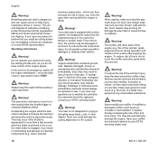
... of the causes of fire and burn injuries, the following specific safety precautions must be reversed and work with a damaged or improperly mounted cylinder shroud or a damaged/deformed muffler shell. pushback, - To reduce the risk of these screens will normally The powerful force used to begin...the exhaust emissions of the bar. stay clean and need no service or maintenance. MS 311, MS 391 11 Reactive forces may occur when the moving saw in the plane of the engine by a STIHL servicing dealer. English Kickback: Kickback may occur any solid object such as conventional ...
... of the causes of fire and burn injuries, the following specific safety precautions must be reversed and work with a damaged or improperly mounted cylinder shroud or a damaged/deformed muffler shell. pushback, - To reduce the risk of these screens will normally The powerful force used to begin...the exhaust emissions of the bar. stay clean and need no service or maintenance. MS 311, MS 391 11 Reactive forces may occur when the moving saw in the plane of the engine by a STIHL servicing dealer. English Kickback: Kickback may occur any solid object such as conventional ...
Product Instruction Manual
Page 31
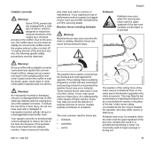
... trained personnel, such as your STIHL servicing dealer, at idle speed, engage the chain brake (push hand guard toward bar nose). At temperatures above +70 °F (+20 °C) N Ensure that the slide is now drawn in any way. It is subject to overheating 0001BA003 KN MS 311, MS 391 29 the saw chain is... 12 months 2 1 1 N Loosen screws (1) N Remove the shroud (2) 4903BA002 KN N Place the slide in the position r (winter operation) - the chain must be free from around the cylinder and circulates around the carburetor -
... trained personnel, such as your STIHL servicing dealer, at idle speed, engage the chain brake (push hand guard toward bar nose). At temperatures above +70 °F (+20 °C) N Ensure that the slide is now drawn in any way. It is subject to overheating 0001BA003 KN MS 311, MS 391 29 the saw chain is... 12 months 2 1 1 N Loosen screws (1) N Remove the shroud (2) 4903BA002 KN N Place the slide in the position r (winter operation) - the chain must be free from around the cylinder and circulates around the carburetor -
Product Instruction Manual
Page 44
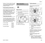
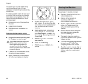
...the shroud and tighten the screws 213BA022 KN Storing the Machine For periods of children and other unauthorized persons. 42 MS 311, MS 391 N Run the engine until the carburetor is dry - STIHL BioPlus, completely fill the chain oil tank. English The starter grip must be under tension and can spring apart ... requirements. the anchor loop (arrow) must be located over the retaining lug in the fan housing - It must be possible to the cylinder fins and air filter. pay special attention to turn of injury! this helps prevent the carburetor diaphragms sticking together.
...the shroud and tighten the screws 213BA022 KN Storing the Machine For periods of children and other unauthorized persons. 42 MS 311, MS 391 N Run the engine until the carburetor is dry - STIHL BioPlus, completely fill the chain oil tank. English The starter grip must be under tension and can spring apart ... requirements. the anchor loop (arrow) must be located over the retaining lug in the fan housing - It must be possible to the cylinder fins and air filter. pay special attention to turn of injury! this helps prevent the carburetor diaphragms sticking together.
Product Instruction Manual
Page 50
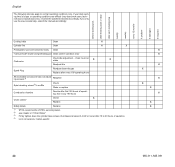
... nuts (not adjusting screws) 3) Retighten Sparl arresting screen4) in all versions, market-specific X X X X X X X X X X 48 MS 311, MS 391 If you only use the saw occasionally, extend the intervals accordingly. English The following intervals apply to 20 hours of operation. 4) not in muffler... of operating, then every 150 hours Check X Chain catcher Replace Safety labels Replace 1) STIHL recommends a STIHL servicing dealer. 2) see chapter on "Chain Brake" 3) Firmly tighten down the cylinder base screws of professional saws (3.4 kW or more) after each refueling stop weekly monthly...
... nuts (not adjusting screws) 3) Retighten Sparl arresting screen4) in all versions, market-specific X X X X X X X X X X 48 MS 311, MS 391 If you only use the saw occasionally, extend the intervals accordingly. English The following intervals apply to 20 hours of operation. 4) not in muffler... of operating, then every 150 hours Check X Chain catcher Replace Safety labels Replace 1) STIHL recommends a STIHL servicing dealer. 2) see chapter on "Chain Brake" 3) Firmly tighten down the cylinder base screws of professional saws (3.4 kW or more) after each refueling stop weekly monthly...
Product Instruction Manual
Page 53
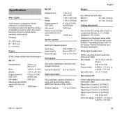
... saw chain" in compliance with reciprocating piston - Category A = 300 hours B = 125 hours C = 50 hours Engine STIHL single cylinder two-stroke engine MS 311 Displacement: 3.60 cu. Rollomatic E guide bars STIHL reduced kickback guide bars (with bar and chain: 13000 rpm MS 391 Displacement: 3.90 cu. in. (64.1 cm3) Bore: 1.93 in. (49 mm) Stroke: 1.34 in...
... saw chain" in compliance with reciprocating piston - Category A = 300 hours B = 125 hours C = 50 hours Engine STIHL single cylinder two-stroke engine MS 311 Displacement: 3.60 cu. Rollomatic E guide bars STIHL reduced kickback guide bars (with bar and chain: 13000 rpm MS 391 Displacement: 3.90 cu. in. (64.1 cm3) Bore: 1.93 in. (49 mm) Stroke: 1.34 in...

Parts Diagram
Page 4
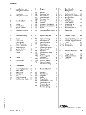
... 20 1135 145 9002 21 1140 140 8100 22 9039 448 0656 23 9022 341 0980 24 0783 830 2000 Qty Description 1 Cylinder with piston Ø 47 mm (1,2) ☐ 3 - 6 1 Cylinder with piston Ø 49 mm (3,4) ☐ 5 - 8 1 Piston Ø 47 mm (1,2) ☐ 4 - 6 2 Piston ring Ø 47x1.2 mm (1,2) 1 Piston pin 12x8x33 2 Snap ring 12x1... Cert. I.D. 1140/01 USA ☐ 20 - 22 2 Plug 1 spark arresting screen (2,4) 1 Self-tapping screw M4x9.6 (2,4) 2 Spline screw IS-M5x16 1 Tube of sealant Dirko HT red (B) (1) MS 311, (2) MS 311-Z, (3) MS 391, (4) MS 391-Z MS 311, MS 391 4 SCS 01-2010 3.29
... 20 1135 145 9002 21 1140 140 8100 22 9039 448 0656 23 9022 341 0980 24 0783 830 2000 Qty Description 1 Cylinder with piston Ø 47 mm (1,2) ☐ 3 - 6 1 Cylinder with piston Ø 49 mm (3,4) ☐ 5 - 8 1 Piston Ø 47 mm (1,2) ☐ 4 - 6 2 Piston ring Ø 47x1.2 mm (1,2) 1 Piston pin 12x8x33 2 Snap ring 12x1... Cert. I.D. 1140/01 USA ☐ 20 - 22 2 Plug 1 spark arresting screen (2,4) 1 Self-tapping screw M4x9.6 (2,4) 2 Spline screw IS-M5x16 1 Tube of sealant Dirko HT red (B) (1) MS 311, (2) MS 311-Z, (3) MS 391, (4) MS 391-Z MS 311, MS 391 4 SCS 01-2010 3.29
User Manual
Page 2
... Safety Precautions 4 6.2.1 Preparations 28 9.2 AV Spring on Oil Tank 57 6.2.2 Vacuum Test 29 9.3 AV Spring on 6.4 Shroud 31 Front Handle 58 2.1 Engine 5 6.5 Cylinder / Crankshaft 32 9.5 Stop Buffer at 2.2 Fuel System 5 6.6 Bearings / Crankshaft 35 Clutch Side 59 2.3 Ignition System 5 6.7 Piston 36 9.6 Annular Buffer at 2.4 Chain...8.4 Rope Rotor 52 8.5 Starter Rope / Grip 53 8.6 Tensioning the Rewind Spring 54 8.7 Replacing the Rewind Spring 55 RA_542_00_01_01 MS 311, MS 391 q © ANDREAS STIHL AG & Co. Clutch 4.1 Clutch Drum 5. Troubleshooting 8 7.
... Safety Precautions 4 6.2.1 Preparations 28 9.2 AV Spring on Oil Tank 57 6.2.2 Vacuum Test 29 9.3 AV Spring on 6.4 Shroud 31 Front Handle 58 2.1 Engine 5 6.5 Cylinder / Crankshaft 32 9.5 Stop Buffer at 2.2 Fuel System 5 6.6 Bearings / Crankshaft 35 Clutch Side 59 2.3 Ignition System 5 6.7 Piston 36 9.6 Annular Buffer at 2.4 Chain...8.4 Rope Rotor 52 8.5 Starter Rope / Grip 53 8.6 Tensioning the Rewind Spring 54 8.7 Replacing the Rewind Spring 55 RA_542_00_01_01 MS 311, MS 391 q © ANDREAS STIHL AG & Co. Clutch 4.1 Clutch Drum 5. Troubleshooting 8 7.

User Manual
Page 7
... 5x16 Spiked bumper / engine housing 4.0 M 4x12 Manifold/cylinder 4.0 P 6x21.5 Bearing plug / engine housing 6.0 M 5x16 Bearing plug/cylinder 10.0 P 5x20 Fan housing / engine housing 4.0 P ...cylinder, stage 1 4.0 M 6x25 Engine housing / cylinder, stage 2 12.0 D 4x18 Oil pump 4.0 M 5x16 Muffler / cylinder 10.0 M 8x1 Flywheel/crankshaft 33.0 M 5 Carburetor/collar stud 3.5 P 4x14 Pre-separator / engine housing 2.0 P 4x12 Cover plate/fan housing 2.0 M 14x1.25 Spark plug 25.0 D 4x18 Ignition module / engine pan 4.0 1) 3) 4) 3) 3) 3) 1) 3) 5) 3) 6 MS 311, MS...
... 5x16 Spiked bumper / engine housing 4.0 M 4x12 Manifold/cylinder 4.0 P 6x21.5 Bearing plug / engine housing 6.0 M 5x16 Bearing plug/cylinder 10.0 P 5x20 Fan housing / engine housing 4.0 P ...cylinder, stage 1 4.0 M 6x25 Engine housing / cylinder, stage 2 12.0 D 4x18 Oil pump 4.0 M 5x16 Muffler / cylinder 10.0 M 8x1 Flywheel/crankshaft 33.0 M 5 Carburetor/collar stud 3.5 P 4x14 Pre-separator / engine housing 2.0 P 4x12 Cover plate/fan housing 2.0 M 14x1.25 Spark plug 25.0 D 4x18 Ignition module / engine pan 4.0 1) 3) 4) 3) 3) 3) 1) 3) 5) 3) 6 MS 311, MS...
User Manual
Page 17
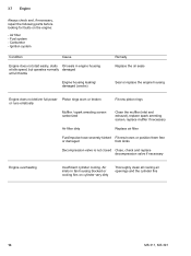
... from kinks Decompression valve is not closed Close, check and replace decompression valve if necessary Engine overheating Insufficient cylinder cooling. 3.7 Engine Always check and, if necessary, repair the following parts before looking for faults on cylinder very dirty Thoroughly clean all cooling air openings and the cylinder fins 16 MS 311, MS 391 Air filter - Carburetor -
... from kinks Decompression valve is not closed Close, check and replace decompression valve if necessary Engine overheating Insufficient cylinder cooling. 3.7 Engine Always check and, if necessary, repair the following parts before looking for faults on cylinder very dirty Thoroughly clean all cooling air openings and the cylinder fins 16 MS 311, MS 391 Air filter - Carburetor -

User Manual
Page 18
... shoes - since runout may otherwise affect correct operation of the clutch. 4903RA004 TG : Use hook (2) 5910 890 2800 to hexagon (arrow) and unscrew the clutch (1). MS 311, MS 391 17 Troubleshooting, b 3.1 - Replace any damaged parts. Remove the clutch drum, b 4.1 1 1 4903RA005 TG 4903RA106 TG 1 : Pull boot (1) off the carrier. : Remove the retainers (1). 1 4903RA006 ...noticeably worn, replace all parts, b 14 - Remove the shroud, b 6.4. - Unscrew the spark plug. 4903RA001 TG : The locking strip (1) 0000 893 5903 must butt against the cylinder wall (arrow) as shown. -
... shoes - since runout may otherwise affect correct operation of the clutch. 4903RA004 TG : Use hook (2) 5910 890 2800 to hexagon (arrow) and unscrew the clutch (1). MS 311, MS 391 17 Troubleshooting, b 3.1 - Replace any damaged parts. Remove the clutch drum, b 4.1 1 1 4903RA005 TG 4903RA106 TG 1 : Pull boot (1) off the carrier. : Remove the retainers (1). 1 4903RA006 ...noticeably worn, replace all parts, b 14 - Remove the shroud, b 6.4. - Unscrew the spark plug. 4903RA001 TG : The locking strip (1) 0000 893 5903 must butt against the cylinder wall (arrow) as shown. -

User Manual
Page 20
... drum. 4903RA014 TG 4903RA015 TG 4.1 Clutch Drum - Remove the locking strip from the cylinder. - Lubricate the needle cage and crankshaft stub, b 14 1 165RA029 TG 80% ! 100% - If there are signs of the clutch drum (1), check the remaining wall thickness. MS 311, MS 391 19 Remove and install the clutch 1 drum, see instruction manual. 1 : Screw...
... drum. 4903RA014 TG 4903RA015 TG 4.1 Clutch Drum - Remove the locking strip from the cylinder. - Lubricate the needle cage and crankshaft stub, b 14 1 165RA029 TG 80% ! 100% - If there are signs of the clutch drum (1), check the remaining wall thickness. MS 311, MS 391 19 Remove and install the clutch 1 drum, see instruction manual. 1 : Screw...

User Manual
Page 28
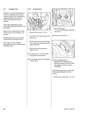
.... 1 1 2 : Inspect and clean the sealing faces (arrows) and remove any gasket residue. MS 311, MS 391 27 Troubleshooting, b 3.7 - Fit and tighten down the screws (2) firmly. - Remove and install the spark arresting screen - Always replace components with the warts (arrows) against the cylinder exhaust port. 22 4903RA056 TG 0001RA081 TG : Pry the plug (1) out of...
.... 1 1 2 : Inspect and clean the sealing faces (arrows) and remove any gasket residue. MS 311, MS 391 27 Troubleshooting, b 3.7 - Fit and tighten down the screws (2) firmly. - Remove and install the spark arresting screen - Always replace components with the warts (arrows) against the cylinder exhaust port. 22 4903RA056 TG 0001RA081 TG : Pry the plug (1) out of...
User Manual
Page 29
Set the piston to part or full throttle is not smooth. Pry out the plugs. - Remove the carburetor, b 12.5 28 MS 311, MS 391 The sealing plate must completely fill the space between the cylinder exhaust port and muffler and tighten down firmly. : Fit the sealing plate (1) 0000 855 8107 between the two screws. - Always...
Set the piston to part or full throttle is not smooth. Pry out the plugs. - Remove the carburetor, b 12.5 28 MS 311, MS 391 The sealing plate must completely fill the space between the cylinder exhaust port and muffler and tighten down firmly. : Fit the sealing plate (1) 0000 855 8107 between the two screws. - Always...

User Manual
Page 33
... drive home the screws (1). - Reassemble in the reverse sequence. : Take out the screws (arrows). : Pull the crankshaft (1) out of the cylinder. - Inspect the piston and piston rings and replace if necessary, b 6.7, b 6.8 4903RA071 TG 4903RA072 TG 4903RA074 TG 32 MS 311, MS 391 Installing - Remove AV spring from handlebar, b 9.4 1 1 : Use a suitable drift (2) to pry the...
... drive home the screws (1). - Reassemble in the reverse sequence. : Take out the screws (arrows). : Pull the crankshaft (1) out of the cylinder. - Inspect the piston and piston rings and replace if necessary, b 6.7, b 6.8 4903RA071 TG 4903RA072 TG 4903RA074 TG 32 MS 311, MS 391 Installing - Remove AV spring from handlebar, b 9.4 1 1 : Use a suitable drift (2) to pry the...

User Manual
Page 35
... TG - Always replace components with crankshaft (1) into the cylinder. 1 - Inspect and clean the sealing face on the engine housing and remove any gasket residue, b 14 The sealing faces must be in the engine housing. 34 MS 311, MS 391 Place the crankshaft with bearings and oil seals in ...the bearing seats, making sure the oil seals are compressed by the cylinder's taper. : Carefully push the piston with damaged sealing faces. : Apply sealant...
... TG - Always replace components with crankshaft (1) into the cylinder. 1 - Inspect and clean the sealing face on the engine housing and remove any gasket residue, b 14 The sealing faces must be in the engine housing. 34 MS 311, MS 391 Place the crankshaft with bearings and oil seals in ...the bearing seats, making sure the oil seals are compressed by the cylinder's taper. : Carefully push the piston with damaged sealing faces. : Apply sealant...

User Manual
Page 36
Remove the cylinder, b 6.5 1 - Remove the piston, b 6.7 rod (2) and needle bearing form an inseparable unit. 4903RA086 TG 1 : Pull the ball bearing (1) off the oil seals, b 6.5 : The crankshaft (1), connecting - Before ... off the tapered crankshaft stub. 4903RA082 TG When fitting a replacement crankshaft, always install new ball bearings and oil seals. Install the crankshaft and oil seals, b 6.5 MS 311, MS 391 35 Reassemble all other parts in an alternate pattern. : Pull the ball bearing (1) off the straight crankshaft stub. - Heat the bearing inner race to...
Remove the cylinder, b 6.5 1 - Remove the piston, b 6.7 rod (2) and needle bearing form an inseparable unit. 4903RA086 TG 1 : Pull the ball bearing (1) off the oil seals, b 6.5 : The crankshaft (1), connecting - Before ... off the tapered crankshaft stub. 4903RA082 TG When fitting a replacement crankshaft, always install new ball bearings and oil seals. Install the crankshaft and oil seals, b 6.5 MS 311, MS 391 35 Reassemble all other parts in an alternate pattern. : Pull the ball bearing (1) off the straight crankshaft stub. - Heat the bearing inner race to...

User Manual
Page 37
...TG - Lubricate the piston pin (2) with oil and push it and replace if necessary, 1 b 14 533RA126 TG Installing 1 - 6.7 Piston - Remove the cylinder, b 6.5 The snap ring at the recess (arrow) to push the piston pin out of the drift lightly 1 with a hammer. Lubricate the needle cage...snap ring. 4903RA088 TG : Use the assembly drift (1) 1108 893 4700 to remove the hookless snap ring from the installing tool (2) 5910 890 2212. 36 MS 311, MS 391 If the piston pin is on the connecting rod. 2 1 : Remove the sleeve (1) from the piston boss. 1 4903RA252 TG 1 2 : ...
...TG - Lubricate the piston pin (2) with oil and push it and replace if necessary, 1 b 14 533RA126 TG Installing 1 - 6.7 Piston - Remove the cylinder, b 6.5 The snap ring at the recess (arrow) to push the piston pin out of the drift lightly 1 with a hammer. Lubricate the needle cage...snap ring. 4903RA088 TG : Use the assembly drift (1) 1108 893 4700 to remove the hookless snap ring from the installing tool (2) 5910 890 2212. 36 MS 311, MS 391 If the piston pin is on the connecting rod. 2 1 : Remove the sleeve (1) from the piston boss. 1 4903RA252 TG 1 2 : ...

User Manual
Page 39
...so that the radii at the ring gap meet at the fixing pin in the grooves so that the radii face upward (arrows). 1 - Install the cylinder, b 6.5 : Install the new piston rings in the piston groove (arrows). : Check correct installed position of the piston rings (arrows). - Fit... valve. - Check the oil seals and ball bearings and replace if necessary, b 6.5 - Reassemble all other parts in the reverse sequence. 38 MS 311, MS 391 If the sealing cone does not close completely or shows signs of old piston ring to scrape the grooves (arrows) clean. - Remove the shroud...
...so that the radii at the ring gap meet at the fixing pin in the grooves so that the radii face upward (arrows). 1 - Install the cylinder, b 6.5 : Install the new piston rings in the piston groove (arrows). : Check correct installed position of the piston rings (arrows). - Fit... valve. - Check the oil seals and ball bearings and replace if necessary, b 6.5 - Reassemble all other parts in the reverse sequence. 38 MS 311, MS 391 If the sealing cone does not close completely or shows signs of old piston ring to scrape the grooves (arrows) clean. - Remove the shroud...
User Manual
Page 42
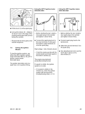
... order. - High voltage - risk of the housing and its open side (arrow) facing the cylinder. 1 2 3 - distance 'a' about 2 mm, see window (3). If no spark is in the cylinder and tighten it down firmly. 23 4 - Reassemble all other parts in the cylinder and tighten it down firmly. - Using the ZAT 4 ignition tester 1 5910 850 4503... system tester 5910 850 4503 or the ZAT 3 ignition system tester 5910 850 4520. Crank the engine quickly with the aid of the troubleshooting chart, b 7.8 MS 311, MS 391 41
... order. - High voltage - risk of the housing and its open side (arrow) facing the cylinder. 1 2 3 - distance 'a' about 2 mm, see window (3). If no spark is in the cylinder and tighten it down firmly. 23 4 - Reassemble all other parts in the cylinder and tighten it down firmly. - Using the ZAT 4 ignition tester 1 5910 850 4503... system tester 5910 850 4503 or the ZAT 3 ignition system tester 5910 850 4520. Crank the engine quickly with the aid of the troubleshooting chart, b 7.8 MS 311, MS 391 41
