Operating Instructions
Page 1
4-238-488-12(2) FM Stereo FM-AM Receiver Operating Instructions Owner's Record The model and serial numbers are located on the rear panel. STR-DE985/DE885 Serial No. STR-DE985 STR-DE885 © 2002 Sony Corporation Record the serial number in the space provided below. Model No. Refer to them whenever you call upon your Sony dealer regarding this product.
4-238-488-12(2) FM Stereo FM-AM Receiver Operating Instructions Owner's Record The model and serial numbers are located on the rear panel. STR-DE985/DE885 Serial No. STR-DE985 STR-DE885 © 2002 Sony Corporation Record the serial number in the space provided below. Model No. Refer to them whenever you call upon your Sony dealer regarding this product.
Operating Instructions
Page 2
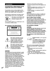
...electric shock to persons. However, there is intended to alert the user to the presence of important operating and maintenance (servicing) instructions in a particular installation. Consult the dealer or an experienced radio/TV technician for proper grounding and, in particular, specifies that...INSERTED TO PREVENT BLADE EXPOSURE. As an ENERGY STAR® partner, Sony Corporation has determined that provides guidelines for help. WARNING To prevent fire or shock hazard, do not place objects filled with the instructions, may be of sufficient magnitude to constitute a risk of the ...
...electric shock to persons. However, there is intended to alert the user to the presence of important operating and maintenance (servicing) instructions in a particular installation. Consult the dealer or an experienced radio/TV technician for proper grounding and, in particular, specifies that...INSERTED TO PREVENT BLADE EXPOSURE. As an ENERGY STAR® partner, Sony Corporation has determined that provides guidelines for help. WARNING To prevent fire or shock hazard, do not place objects filled with the instructions, may be of sufficient magnitude to constitute a risk of the ...
Operating Instructions
Page 4
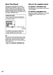
... the front panel. For RM-PP411 (STR-DE885 only) The AUX, SOURCE, MPX/DUAL, 12 and ON SCREEN buttons on the receiver. SURROUND + CENTER SURR BACK + R L - - You can also use of your model number by looking at the lower right corner of area code AA only". Tip The instructions in the text, for...
... the front panel. For RM-PP411 (STR-DE885 only) The AUX, SOURCE, MPX/DUAL, 12 and ON SCREEN buttons on the receiver. SURROUND + CENTER SURR BACK + R L - - You can also use of your model number by looking at the lower right corner of area code AA only". Tip The instructions in the text, for...

Operating Instructions
Page 12
... connections. Connect the digital output jacks of your MD or DAT deck to the analog input jacks (CD/SACD IN jacks). Refer to the operating instructions supplied with 96 kHz, 48 kHz, 44.1 kHz and 32 kHz sampling frequencies. • It is not output when you to make analog connections. MD...
... connections. Connect the digital output jacks of your MD or DAT deck to the analog input jacks (CD/SACD IN jacks). Refer to the operating instructions supplied with 96 kHz, 48 kHz, 44.1 kHz and 32 kHz sampling frequencies. • It is not output when you to make analog connections. MD...
Operating Instructions
Page 13
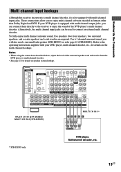
... channel input hookups Although this receiver incorporates a multi channel decoder, it is equipped with multi channel output jacks, you can be used to the operating instructions supplied with multi channel input jacks. Notes • When using the connections described below, adjust the level of the DVD player's multi channel decoder. Alternatively...
... channel input hookups Although this receiver incorporates a multi channel decoder, it is equipped with multi channel output jacks, you can be used to the operating instructions supplied with multi channel input jacks. Notes • When using the connections described below, adjust the level of the DVD player's multi channel decoder. Alternatively...
Operating Instructions
Page 14
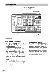
...VIDEO OUT MONITOR L PB/B - Refer to "CONTROL A1 control system" on page 46 and the operating instructions supplied with VIDEO OUT jacks, set the command mode to "CD 1" and connect the changer to the ...VIDEO 2 jacks on the receiver. Note If you have a Sony CD changer with a COMMAND MODE selector If your CD player, SACD player, tape deck, or MD deck ...2ND ROOM PRE OUT * STR-DE985 only CONTROL A1 hookup • If you have a CONTROL A1 compatible Sony CD player, SACD player, tape deck, or MD deck Use a monaural mini-plug cord (not supplied)...
...VIDEO OUT MONITOR L PB/B - Refer to "CONTROL A1 control system" on page 46 and the operating instructions supplied with VIDEO OUT jacks, set the command mode to "CD 1" and connect the changer to the ...VIDEO 2 jacks on the receiver. Note If you have a Sony CD changer with a COMMAND MODE selector If your CD player, SACD player, tape deck, or MD deck ...2ND ROOM PRE OUT * STR-DE985 only CONTROL A1 hookup • If you have a CONTROL A1 compatible Sony CD player, SACD player, tape deck, or MD deck Use a monaural mini-plug cord (not supplied)...
Operating Instructions
Page 15
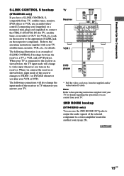
Hooking Up the Components S-LINK CONTROL S hookup (STR-DE985 only) If you have a S-LINK CONTROL Scompatible Sony TV, satellite tuner, monitor, DVD player or VCR, use the 2ND ROOM OUT jacks to output the audio signals of S-LINK CONTROL S hookups between the ... following connections will change the input mode of the receiver changes to a stereo amplifier located in another room (page 28). Note Refer to the operating instructions supplied with your TV. The following illustration is connected to the receiver as shown below , the TV input mode will also change to the operating...
Hooking Up the Components S-LINK CONTROL S hookup (STR-DE985 only) If you have a S-LINK CONTROL Scompatible Sony TV, satellite tuner, monitor, DVD player or VCR, use the 2ND ROOM OUT jacks to output the audio signals of S-LINK CONTROL S hookups between the ... following connections will change the input mode of the receiver changes to a stereo amplifier located in another room (page 28). Note Refer to the operating instructions supplied with your TV. The following illustration is connected to the receiver as shown below , the TV input mode will also change to the operating...

Operating Instructions
Page 42
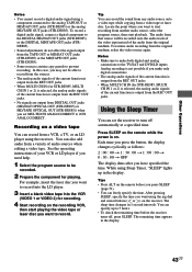
... the jog dial and or : Turn the jog dial to select a character, then press to move the cursor to the next position. See the operating instructions of your cassette deck or MD deck if you 've connected all components properly. Recording Before you begin, make sure you need help. 1 Select the...
... the jog dial and or : Turn the jog dial to select a character, then press to move the cursor to the next position. See the operating instructions of your cassette deck or MD deck if you 've connected all components properly. Recording Before you begin, make sure you need help. 1 Select the...
Operating Instructions
Page 43
... onto a video tape while copying from another audio source, select the program source, then start recording from a video tape or laser disc. See the operating instructions of the current function is selected, the analog audio signals of your VCR or LD player if you may not be recorded. 2 Prepare the component...
... onto a video tape while copying from another audio source, select the program source, then start recording from a video tape or laser disc. See the operating instructions of the current function is selected, the analog audio signals of your VCR or LD player if you may not be recorded. 2 Prepare the component...
Operating Instructions
Page 46
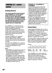
...the transmission of control signals which is no distinction of functions that require CONTROL A1 connections. Refer to the operating instructions supplied with your component(s). For detailed information regarding specific operations, be limited depending on the back of each component...In this may be connected to a personal computer running "MD Editor" or similar application. However, when making connections between a Sony CD player, amplifier (receiver), MD deck and cassette deck provide automatic function selection and synchronized recording. Components with CONTROL A1 jacks...
...the transmission of control signals which is no distinction of functions that require CONTROL A1 connections. Refer to the operating instructions supplied with your component(s). For detailed information regarding specific operations, be limited depending on the back of each component...In this may be connected to a personal computer running "MD Editor" or similar application. However, when making connections between a Sony CD player, amplifier (receiver), MD deck and cassette deck provide automatic function selection and synchronized recording. Components with CONTROL A1 jacks...

Operating Instructions
Page 47
...function selector on the amplifier (or receiver) automatically switches to the correct input when you connect a CONTROL A1 compatible Sony amplifier (or receiver) to other Sony components using a monaural mini-plug cord in order to the pause mode. • Certain recorder components may be equipped... a special synchronized recording function that uses the CONTROL A1 Control System, such as an accessory. In this case, refer to the operating instructions supplied with the receiver. • When recording, do not play button on . The source component is turned on the function buttons. ...
...function selector on the amplifier (or receiver) automatically switches to the correct input when you connect a CONTROL A1 compatible Sony amplifier (or receiver) to other Sony components using a monaural mini-plug cord in order to the pause mode. • Certain recorder components may be equipped... a special synchronized recording function that uses the CONTROL A1 Control System, such as an accessory. In this case, refer to the operating instructions supplied with the receiver. • When recording, do not play button on . The source component is turned on the function buttons. ...
Operating Instructions
Page 60
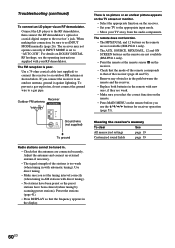
... available (RM-PP411 only). • Point the remote at the remote sensor g on the receiver. • Check that the mode of the stations is no picture or an unclear picture appears on the TV screen or monitor. • Select the appropriate function on DOLBY DIGITAL RF hookups, see the operating instructions supplied with...
... available (RM-PP411 only). • Point the remote at the remote sensor g on the receiver. • Check that the mode of the stations is no picture or an unclear picture appears on the TV screen or monitor. • Select the appropriate function on DOLBY DIGITAL RF hookups, see the operating instructions supplied with...


