
Operating Instructions
Page 1
3-854-213-14 (1) Remote Control Unit Operating Instructions GB Mode d'emploi FR Manual de instrucciones ES Gebrauchsanweisung DE RM-BR300 © 2004 Sony Corporation 3854213140
3-854-213-14 (1) Remote Control Unit Operating Instructions GB Mode d'emploi FR Manual de instrucciones ES Gebrauchsanweisung DE RM-BR300 © 2004 Sony Corporation 3854213140
Operating Instructions
Page 4
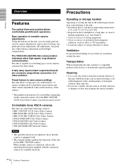
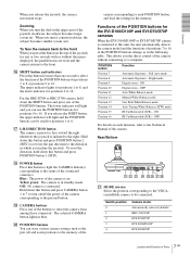
The VISCA RS-232C/RS-422 communication interfaces allow high-speed, long-distance communication. The unit is capable of controlling up to 16 combinations* of camera settings such as pan/tilt/zoom positions and other camera adjustment values in the memory of the camera...versatile camera adjustments Using the buttons on the connected camera. (For the BRC-300/300P 3CCD Color Video Camera, 6 positions can be saved.) Controllable Sony VISCA cameras The unit can be removed using a soft cloth dampened with a small quantity of detergent solution, then wipe dry. • Do not use volatile ...
The VISCA RS-232C/RS-422 communication interfaces allow high-speed, long-distance communication. The unit is capable of controlling up to 16 combinations* of camera settings such as pan/tilt/zoom positions and other camera adjustment values in the memory of the camera...versatile camera adjustments Using the buttons on the connected camera. (For the BRC-300/300P 3CCD Color Video Camera, 6 positions can be saved.) Controllable Sony VISCA cameras The unit can be removed using a soft cloth dampened with a small quantity of detergent solution, then wipe dry. • Do not use volatile ...
Operating Instructions
Page 5
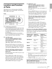
... value of the brightness of the camera, etc. When the BRC-H700 or BRC-Z700 camera is connected, the function of the control with the MODE button of this unit, the functions of the 5 Location and Function of Parts GB qg A LOCK button and indicator Press the LOCK button for more than... one second again to ON. *** Available for the BRC-H700 and BRC-Z700 only Functions of the R and B controls for the BRC-H700 and...
... value of the brightness of the camera, etc. When the BRC-H700 or BRC-Z700 camera is connected, the function of the control with the MODE button of this unit, the functions of the 5 Location and Function of Parts GB qg A LOCK button and indicator Press the LOCK button for more than... one second again to ON. *** Available for the BRC-H700 and BRC-Z700 only Functions of the R and B controls for the BRC-H700 and...
Operating Instructions
Page 6
...AUTO/MANUAL button. Panning and tilting When you incline it again to turn the on-screen data display on a far subject. E FOCUS control This control is enabled when MANUAL is used for about one second to the Operating Instructions of the camera. For details, refer to display the menu... mode AUTO or MANUAL. Press the button to the pressed POSITION button is selected on the subject in the center of the VALUE/R control and BRIGHT/B control. J PANEL LIGHT button Press this button to enable the backlight compensation function of the camera, return to perform the one -push auto...
...AUTO/MANUAL button. Panning and tilting When you incline it again to turn the on-screen data display on a far subject. E FOCUS control This control is enabled when MANUAL is used for about one second to the Operating Instructions of the camera. For details, refer to display the menu... mode AUTO or MANUAL. Press the button to the pressed POSITION button is selected on the subject in the center of the VALUE/R control and BRIGHT/B control. J PANEL LIGHT button Press this button to enable the backlight compensation function of the camera, return to perform the one -push auto...
Operating Instructions
Page 7
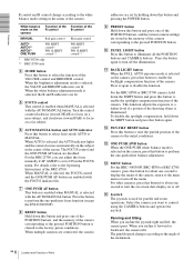
...this button and press POSITION button 1 (STD). Yellow green: The camera is on each POSITION button, and load the settings in which you the direct control of the POSITION buttons. This allows you incline the joystick. OFF For details on . CONTACT(TALLY) TALLY 1 9 1 9 CONTACT DC IN 12V...light and the POSITION buttons can use the POSITION buttons for positions 9 to the pressed button. To reset the direction, hold down this unit, the unit automatically detects the camera model and the functions of positions 7 to 16 of the camera corresponding to 16. S CAMERA buttons Press one...
...this button and press POSITION button 1 (STD). Yellow green: The camera is on each POSITION button, and load the settings in which you the direct control of the POSITION buttons. This allows you incline the joystick. OFF For details on . CONTACT(TALLY) TALLY 1 9 1 9 CONTACT DC IN 12V...light and the POSITION buttons can use the POSITION buttons for positions 9 to the pressed button. To reset the direction, hold down this unit, the unit automatically detects the camera model and the functions of positions 7 to 16 of the camera corresponding to 16. S CAMERA buttons Press one...
Operating Instructions
Page 8
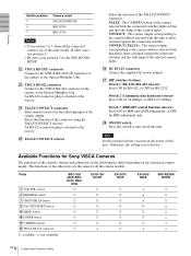
...functions of this unit is used for 9,600bps. Select the function of the TALLY/CONTACT connector. wj DIP switches (bottom) Switch 1 (RS-232C/RS-422 selector) Set to ON for IRIS and GAIN adjustments, or OFF for Sony VISCA Cameras The functions of the controls, buttons and ...on the connected camera model. W VISCA RS-422 connector Connect to the VISCA RS-232C IN connector of the camera or the Optical Multiplex Unit. Parts B VALUE/R control C BRIGHT/B control G ONE PUSH AF button L PAN-TILT RESET button N MENU button R POWER button S CAMERA buttons W VISCA RS-422 connector a: ...
...functions of this unit is used for 9,600bps. Select the function of the TALLY/CONTACT connector. wj DIP switches (bottom) Switch 1 (RS-232C/RS-422 selector) Set to ON for IRIS and GAIN adjustments, or OFF for Sony VISCA Cameras The functions of the controls, buttons and ...on the connected camera model. W VISCA RS-422 connector Connect to the VISCA RS-232C IN connector of the camera or the Optical Multiplex Unit. Parts B VALUE/R control C BRIGHT/B control G ONE PUSH AF button L PAN-TILT RESET button N MENU button R POWER button S CAMERA buttons W VISCA RS-422 connector a: ...
Operating Instructions
Page 10
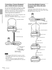
... 1 2 3 OFF ON 75 IR SELECT 1 2 3 4 5 6 7 8 9 VISCA RS-422 ! VISCA RS-232C Camera BRC300/300P to AC outlet RS-232C cable (supplied) (SONY: 1-590-879-3X) to AC outlet VISCA RS-422 VISCA RS-422 cable VISCA RS-422 DC IN 12V AC power cord (supplied) to AC... with the VISCA RS-232C cables (cross type) enable control of up to the pin assignments of this unit (page 8) is not available. For the use the VISCA RS-422 connectors to connect this unit to seven cameras with a single RM-BR300 Remote Control Unit. Connections and Operations Connecting a Camera Equipped with a VISCA...
... 1 2 3 OFF ON 75 IR SELECT 1 2 3 4 5 6 7 8 9 VISCA RS-422 ! VISCA RS-232C Camera BRC300/300P to AC outlet RS-232C cable (supplied) (SONY: 1-590-879-3X) to AC outlet VISCA RS-422 VISCA RS-422 cable VISCA RS-422 DC IN 12V AC power cord (supplied) to AC... with the VISCA RS-232C cables (cross type) enable control of up to the pin assignments of this unit (page 8) is not available. For the use the VISCA RS-422 connectors to connect this unit to seven cameras with a single RM-BR300 Remote Control Unit. Connections and Operations Connecting a Camera Equipped with a VISCA...
Operating Instructions
Page 11
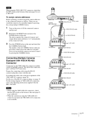
...switch on the bottom of multiple cameras. Connecting Multiple Cameras Equipped with VISCA RS-422 Connector Connection via the VISCA RS-422 connectors enables control of this unit (page 8) is set to RS-422. • When the connections using the RS-422 connector plug that the CAMERA buttons light...VISCA RS-422 cable VISCA RS-422 R 1 2 3 OFF ON 75 IR SELECT 1 2 3 4 5 6 7 8 9 VISCA RS-422 ! For making the cable, refer to control by pressing the corresponding CAMERA button. 1 Turn on the bottom of the RS-422 connector plugs, see page 19. Then you can switch the camera...
...switch on the bottom of multiple cameras. Connecting Multiple Cameras Equipped with VISCA RS-422 Connector Connection via the VISCA RS-422 connectors enables control of this unit (page 8) is set to RS-422. • When the connections using the RS-422 connector plug that the CAMERA buttons light...VISCA RS-422 cable VISCA RS-422 R 1 2 3 OFF ON 75 IR SELECT 1 2 3 4 5 6 7 8 9 VISCA RS-422 ! For making the cable, refer to control by pressing the corresponding CAMERA button. 1 Turn on the bottom of the RS-422 connector plugs, see page 19. Then you can switch the camera...
Operating Instructions
Page 12
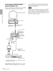
... camera with this unit (page 8) are set to control the 12 GB Connections R 1 2 3 OFF ON 75 IR SELECT 1 2 3 4 5 6 7 8 9 VISCA RS-422 ! For the BRC-H700 or BRC-Z700 camera, you use the BRU-H700 Optical Multiplex Unit to RS-232C or RS-422 correctly. RS-232C cable (supplied)* (SONY: 1-590-879-3X...) VISCA RS-232C to AC outlet * The VISCA RS-422 connection is also available if you can control the camera using the VISCA RS-232C connectors or...
... camera with this unit (page 8) are set to control the 12 GB Connections R 1 2 3 OFF ON 75 IR SELECT 1 2 3 4 5 6 7 8 9 VISCA RS-422 ! For the BRC-H700 or BRC-Z700 camera, you use the BRU-H700 Optical Multiplex Unit to RS-232C or RS-422 correctly. RS-232C cable (supplied)* (SONY: 1-590-879-3X...) VISCA RS-232C to AC outlet * The VISCA RS-422 connection is also available if you can control the camera using the VISCA RS-232C connectors or...
Operating Instructions
Page 13
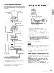
... long as the camera is turned on this unit, the POWER lamp turns off the camera using this unit. EXT SYNC IN VIDEO S VIDEO IN VISCA RS-232C OUT DC IN 12V VISCA RS-232C IN RS-232C cable (supplied) (SONY: 1-590-879-3X) VISCA RS-232C MODE RS-232C VISCA ... devices. For connection with the POWER button on and the POWER lamp lights. Connections and Operations Connecting a Video Switcher Use a commercially available contact-control type video switcher to switch between the multiple camera signals to the Operating Instructions of the origin. Turning on the video switcher.
... long as the camera is turned on this unit, the POWER lamp turns off the camera using this unit. EXT SYNC IN VIDEO S VIDEO IN VISCA RS-232C OUT DC IN 12V VISCA RS-232C IN RS-232C cable (supplied) (SONY: 1-590-879-3X) VISCA RS-232C MODE RS-232C VISCA ... devices. For connection with the POWER button on and the POWER lamp lights. Connections and Operations Connecting a Video Switcher Use a commercially available contact-control type video switcher to switch between the multiple camera signals to the Operating Instructions of the origin. Turning on the video switcher.
Operating Instructions
Page 16
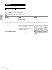
Appendix Troubleshooting Before bringing in your Sony dealer. The AC power adaptor is not connected to the Insert the power cord firmly... is not inserted firmly into the AC outlet after a while. VISCA control setting is not turned on the unit (page 8). go . Pull out the plug of the camera and the unit differ. The camera cannot be operated with the DIP switch on . ... the power cord from the - Select the communication baud rate, 9,600 bps or 38,400 bps, with your unit for service, check the following as it into Insert the power cord firmly as far as it will DC IN ...
Appendix Troubleshooting Before bringing in your Sony dealer. The AC power adaptor is not connected to the Insert the power cord firmly... is not inserted firmly into the AC outlet after a while. VISCA control setting is not turned on the unit (page 8). go . Pull out the plug of the camera and the unit differ. The camera cannot be operated with the DIP switch on . ... the power cord from the - Select the communication baud rate, 9,600 bps or 38,400 bps, with your unit for service, check the following as it into Insert the power cord firmly as far as it will DC IN ...
Operating Instructions
Page 17
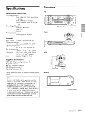
...8pin type VISCA RS-422: 9-pin type TALLY IN/CONTACT OUT: 9-pin type Control signal format 9,600 bps/38,400 bps Data: 8 bit Stop bit: 1 ... 5 3/4 inches) Approx. 950 g (2 lb 15 oz) Supplied accessories MPA-AC1 AC power adaptor (Sony) (1) AC power cord (1) RS-232C connecting cable (1) RS-422 connector plug (2) Operating Instructions (1) Design and specifications are subject to ...COMPENSATION OR REIMBURSEMENT ON ACCOUNT OF THE LOSS OF PRESENT OR PROSPECTIVE PROFITS DUE TO FAILURE OF THIS UNIT, EITHER DURING THE WARRANTY PERIOD OR AFTER EXPIRATION OF THE WARRANTY, OR FOR ANY OTHER REASON WHATSOEVER....
...8pin type VISCA RS-422: 9-pin type TALLY IN/CONTACT OUT: 9-pin type Control signal format 9,600 bps/38,400 bps Data: 8 bit Stop bit: 1 ... 5 3/4 inches) Approx. 950 g (2 lb 15 oz) Supplied accessories MPA-AC1 AC power adaptor (Sony) (1) AC power cord (1) RS-232C connecting cable (1) RS-422 connector plug (2) Operating Instructions (1) Design and specifications are subject to ...COMPENSATION OR REIMBURSEMENT ON ACCOUNT OF THE LOSS OF PRESENT OR PROSPECTIVE PROFITS DUE TO FAILURE OF THIS UNIT, EITHER DURING THE WARRANTY PERIOD OR AFTER EXPIRATION OF THE WARRANTY, OR FOR ANY OTHER REASON WHATSOEVER....


