
Operating Instructions
Page 11
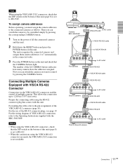
... the lit CAMERA buttons indicates how many cameras have the addresses assigned. For the wiring diagram of VISCA RS-422 connection, refer to the Operating Instructions supplied with VISCA RS-422 Connector Connection via the VISCA RS-422 connectors enables control of multiple cameras. The unit recognizes the connected cameras and assigns them camera addresses 1 to 7 automatically in the...
... the lit CAMERA buttons indicates how many cameras have the addresses assigned. For the wiring diagram of VISCA RS-422 connection, refer to the Operating Instructions supplied with VISCA RS-422 Connector Connection via the VISCA RS-422 connectors enables control of multiple cameras. The unit recognizes the connected cameras and assigns them camera addresses 1 to 7 automatically in the...
Operating Instructions
Page 19
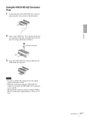
... approximately 1,200 m (3,937 feet). 19 Specifications GB Appendix Using the VISCA RS-422 Connector Plug 1 Grasp both ends of the VISCA RS-422 connector plug and pull it out as shown in the illustration. 1 9 2 Insert a wire (AWG Nos. 28 to 18) into the VISCA RS-422 connector. 1 9 Notes • In order to stabilize the voltage level of...
... approximately 1,200 m (3,937 feet). 19 Specifications GB Appendix Using the VISCA RS-422 Connector Plug 1 Grasp both ends of the VISCA RS-422 connector plug and pull it out as shown in the illustration. 1 9 2 Insert a wire (AWG Nos. 28 to 18) into the VISCA RS-422 connector. 1 9 Notes • In order to stabilize the voltage level of...

