Operating Instructions
Page 3
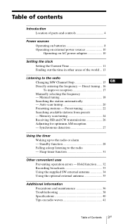
... uses Preventing operation errors - Preset tuning 22 Searching available stations from presets - Standby function 28 Falling asleep listening to the radio or alarm - Hold function ....... 32 Recording broadcasts 33 Using the supplied SW external antenna 34 Using the optional external antenna... Using the timer Waking up to the radio - Manual tuning 18 Searching the station automatically - Table of contents Introduction Location of parts and controls 4 Power sources Operating on batteries 8 Operating on external power sources 10 Operating on radio waves 41 Table of the world ... ...
... uses Preventing operation errors - Preset tuning 22 Searching available stations from presets - Standby function 28 Falling asleep listening to the radio or alarm - Hold function ....... 32 Recording broadcasts 33 Using the supplied SW external antenna 34 Using the optional external antenna... Using the timer Waking up to the radio - Manual tuning 18 Searching the station automatically - Table of contents Introduction Location of parts and controls 4 Power sources Operating on batteries 8 Operating on external power sources 10 Operating on radio waves 41 Table of the world ... ...
Operating Instructions
Page 5
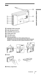
Base qj Stand Pull out qk Battery compartment Introduction 5GB Furthermore, do not use . At this time, be sure to push in the base as well. Rear Location of parts and controls qa SSB FINE TUNE control (26) qs LSB/USB selector (26, 27) qd AM MODE selector (26, 27) qf TONE selector (33) qg VOLUME control qh Telescopic antenna Always pull out the base of the antenna before use unnecessary force when storing the antenna.
Base qj Stand Pull out qk Battery compartment Introduction 5GB Furthermore, do not use . At this time, be sure to push in the base as well. Rear Location of parts and controls qa SSB FINE TUNE control (26) qs LSB/USB selector (26, 27) qd AM MODE selector (26, 27) qf TONE selector (33) qg VOLUME control qh Telescopic antenna Always pull out the base of the antenna before use unnecessary force when storing the antenna.
Operating Instructions
Page 7
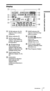
... timer is in effect. 8 STANDBY , STANDBY indicators (28, 29, 30) Light up when the standby timer is set. 9 PAGE number display Appears constantly when the radio is in . 2 Battery indicator (9) 3 HOLD indicator (32) Appears when HOLD is on. 0 Time/frequency display Introduction 7GB
... timer is in effect. 8 STANDBY , STANDBY indicators (28, 29, 30) Light up when the standby timer is set. 9 PAGE number display Appears constantly when the radio is in . 2 Battery indicator (9) 3 HOLD indicator (32) Appears when HOLD is on. 0 Time/frequency display Introduction 7GB
Operating Instructions
Page 8
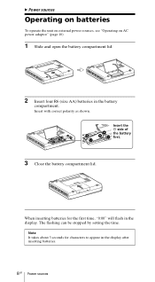
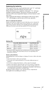
... in the display. The flashing can be stopped by setting the time. Insert with correct polarity as shown. When inserting batteries for characters to appear in the battery compartment. B Power sources Operating on batteries To operate the unit on external power sources, see "Operating on AC power adaptor" (page 10). 1 Slide and open...
... in the display. The flashing can be stopped by setting the time. Insert with correct polarity as shown. When inserting batteries for characters to appear in the battery compartment. B Power sources Operating on batteries To operate the unit on external power sources, see "Operating on AC power adaptor" (page 10). 1 Slide and open...
Operating Instructions
Page 9
... correct polarity. • Do not mix new and used for a long time. • Do not carry the dry batteries with coins or other metallic objects. Battery life (JEITA*) Sony LR6 alkaline (size AA) Sony R6 (size AA) FM approx. 47 hours approx. 15 hours SW approx. 34 hours approx. 10 hours MW/LW approx...
... correct polarity. • Do not mix new and used for a long time. • Do not carry the dry batteries with coins or other metallic objects. Battery life (JEITA*) Sony LR6 alkaline (size AA) Sony R6 (size AA) FM approx. 47 hours approx. 15 hours SW approx. 34 hours approx. 10 hours MW/LW approx...

Operating Instructions
Page 10
... in . • Use only the recommended AC power adaptor manufactured by connecting the AC power adaptor to be operated by Sony. Do not place heavy objects on batteries, first disconnect the AC power adaptor from the wall outlet, then disconnect the AC power adaptor from the wall outlet and... radio when the unit is connected, the unit automatically switches to the external power source, regardless of the plug, etc.) will not...
... in . • Use only the recommended AC power adaptor manufactured by connecting the AC power adaptor to be operated by Sony. Do not place heavy objects on batteries, first disconnect the AC power adaptor from the wall outlet, then disconnect the AC power adaptor from the wall outlet and... radio when the unit is connected, the unit automatically switches to the external power source, regardless of the plug, etc.) will not...
Operating Instructions
Page 11
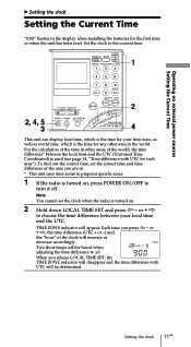
...area in the world. Each time you are in. * This unit uses time zones to pinpoint specific areas. 1 If the radio is turned on, press POWER ON/OFF to the current time. 1 2 2, 4, 5 3 4 This unit can display..., which is the time for any other areas of the time in the display when installing the batteries for each area"). Note You cannot set the correct time and time difference of the clock will...the clock to turn it off. To find out the correct time, set the clock when the radio is used (see page 14, "Time difference with UTC will disappear and the time difference with UTC...
...area in the world. Each time you are in. * This unit uses time zones to pinpoint specific areas. 1 If the radio is turned on, press POWER ON/OFF to the current time. 1 2 2, 4, 5 3 4 This unit can display..., which is the time for any other areas of the time in the display when installing the batteries for each area"). Note You cannot set the correct time and time difference of the clock will...the clock to turn it off. To find out the correct time, set the clock when the radio is used (see page 14, "Time difference with UTC will disappear and the time difference with UTC...
Operating Instructions
Page 36
...; The unit is not disconnected from possible damage caused by qualified personnel before operating it with a soft dry cloth dampened with four R6 (size AA) batteries.
...; The unit is not disconnected from possible damage caused by qualified personnel before operating it with a soft dry cloth dampened with four R6 (size AA) batteries.
Operating Instructions
Page 38
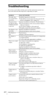
...no sound output. c Properly connect the AC power adaptor. c Unplug the headphones. c Insert the batteries with new batteries. c Set ATT switch to the radio near a window when in the direction opposite the arrow (to ON. c Hold down completely. Cannot... complete direct tuning. Cannot preset a station. Weak batteries. Replace with correct polarity. c Replace with correct polarity. Weak radio signal. Incorrect procedure. Improper installation of batteries. c Adjust tuning and antenna properly. c Listen to OFF (page 21...
...no sound output. c Properly connect the AC power adaptor. c Unplug the headphones. c Insert the batteries with new batteries. c Set ATT switch to the radio near a window when in the direction opposite the arrow (to ON. c Hold down completely. Cannot... complete direct tuning. Cannot preset a station. Weak batteries. Replace with correct polarity. c Replace with correct polarity. Weak radio signal. Incorrect procedure. Improper installation of batteries. c Adjust tuning and antenna properly. c Listen to OFF (page 21...

Operating Instructions
Page 39
... switch to ON. No frequencies are not station presets in the STANDBY MEMORY. The volume is activated. Cause and remedies You forgot to replace the batteries. c Set the correct time. There are stored in the page to disappear "-") (page 32). Troubleshooting Additional information 39GB c Press STANDBY MEMORY or (page 29). Symptom...
... switch to ON. No frequencies are not station presets in the STANDBY MEMORY. The volume is activated. Cause and remedies You forgot to replace the batteries. c Set the correct time. There are stored in the page to disappear "-") (page 32). Troubleshooting Additional information 39GB c Press STANDBY MEMORY or (page 29). Symptom...
Operating Instructions
Page 40
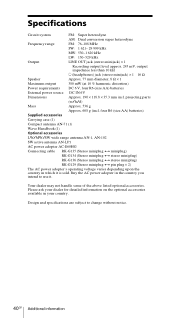
... handle some of the above listed optional accessories. Design and specifications are subject to use it is sold. four R6 (size AA) batteries) Supplied accessories Carrying case (1) Compact antenna AN-71 (1) Wave Handbook (1) Optional accessories LW/MW/SW wide range antenna AN-1, AN-102 ... Speaker Approx. 77 mm diameter, 8 Ω × 1 Maximum output 380 mW (at 10 % harmonic distortion) Power requirements DC 6 V, four R6 (size AA) batteries External power source DC IN 6V Dimensions Approx. 190 × 118.8 × 35.3 mm incl. Buy the AC power adopter in the country you intend...
... handle some of the above listed optional accessories. Design and specifications are subject to use it is sold. four R6 (size AA) batteries) Supplied accessories Carrying case (1) Compact antenna AN-71 (1) Wave Handbook (1) Optional accessories LW/MW/SW wide range antenna AN-1, AN-102 ... Speaker Approx. 77 mm diameter, 8 Ω × 1 Maximum output 380 mW (at 10 % harmonic distortion) Power requirements DC 6 V, four R6 (size AA) batteries External power source DC IN 6V Dimensions Approx. 190 × 118.8 × 35.3 mm incl. Buy the AC power adopter in the country you intend...
Service Manual
Page 1
...(incl. four R6 (size AA) batteries) Supplied accessories Carrying case (1) Compact antenna AN-71 (1) Wave Handbook (1) Design and specifications are subject to change without notice. 9-873-099-11 2001C1600-1 © 2001.3 Sony Corporation Audio Entertainment Group General Engineering Dept. ICF-SW7600GR SERVICE MANUAL Ver 1.0 2001. 03 US... diameter, 8 Ω × 1 Maximum output 380 mW (at 10 % harmonic distortion) Power requirements DC 6 V, four R6 (size AA) batteries External power source DC IN 6V (except Chinese) Dimensions Approx. 190 × 118.8 × 35.3 mm incl.
...(incl. four R6 (size AA) batteries) Supplied accessories Carrying case (1) Compact antenna AN-71 (1) Wave Handbook (1) Design and specifications are subject to change without notice. 9-873-099-11 2001C1600-1 © 2001.3 Sony Corporation Audio Entertainment Group General Engineering Dept. ICF-SW7600GR SERVICE MANUAL Ver 1.0 2001. 03 US... diameter, 8 Ω × 1 Maximum output 380 mW (at 10 % harmonic distortion) Power requirements DC 6 V, four R6 (size AA) batteries External power source DC IN 6V (except Chinese) Dimensions Approx. 190 × 118.8 × 35.3 mm incl.
Service Manual
Page 3
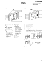
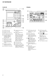
Performing button operations while the light is on will turn off the light. Base qj Stand Pull out qk Battery compartment 3 When using headphones, sound from instruction manual. 1 AM EXT ANT (AM external antenna) jack (35) 2 ATT (attenuator) control (21) 3 ATT (attenuator) ON/ ...(33) 5 2 (headphones) jack (17, 33) You can enjoy FM stereo broadcasting by connecting the optional stereo headphones to the unit . Front SECTION 1 GENERAL Rear ICF-SW7600GR This section is extracted from the speaker will be sure to push in the base as well. Pressing the button again while the light is...
Performing button operations while the light is on will turn off the light. Base qj Stand Pull out qk Battery compartment 3 When using headphones, sound from instruction manual. 1 AM EXT ANT (AM external antenna) jack (35) 2 ATT (attenuator) control (21) 3 ATT (attenuator) ON/ ...(33) 5 2 (headphones) jack (17, 33) You can enjoy FM stereo broadcasting by connecting the optional stereo headphones to the unit . Front SECTION 1 GENERAL Rear ICF-SW7600GR This section is extracted from the speaker will be sure to push in the base as well. Pressing the button again while the light is...
Service Manual
Page 4
Press again to return to clock display while operating the radio. If you do not press the button, the display will be inoperative. 4 (Daylight Saving Time) indicator (12) Appears when the time display is adjusted to ... (16, 18) Appears when a station is tuned in. 2 Battery indicator (9) 3 HOLD indicator (32) Appears when HOLD is in effect. 8 STANDBY , STANDBY indicators (28, 29, 30) Light up when the standby timer is set. 9 PAGE number display Appears constantly when the radio is in effect. ICF-SW7600GR Controls Display 1 SLEEP button (31) 2 HOLD switch (32...
Press again to return to clock display while operating the radio. If you do not press the button, the display will be inoperative. 4 (Daylight Saving Time) indicator (12) Appears when the time display is adjusted to ... (16, 18) Appears when a station is tuned in. 2 Battery indicator (9) 3 HOLD indicator (32) Appears when HOLD is in effect. 8 STANDBY , STANDBY indicators (28, 29, 30) Light up when the standby timer is set. 9 PAGE number display Appears constantly when the radio is in effect. ICF-SW7600GR Controls Display 1 SLEEP button (31) 2 HOLD switch (32...
Service Manual
Page 5
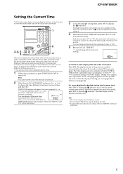
ICF-SW7600GR Setting the Current Time "0:00" flashes in the world. Set the clock to ±0. When you ... areas of the tone. 5 For the calculation of the time in other area in the display when installing the batteries for the first time or when the unit has been reset. Each time you release LOCAL TIME SET, the TIME... " : " starts flashing and the clock starts running. or + k is the time for each area"). During clock display, radio operations such as world time, which is pressed during auto scan (page 20) or memory scan (page 24). The clock will decrease...
ICF-SW7600GR Setting the Current Time "0:00" flashes in the world. Set the clock to ±0. When you ... areas of the tone. 5 For the calculation of the time in other area in the display when installing the batteries for the first time or when the unit has been reset. Each time you release LOCAL TIME SET, the TIME... " : " starts flashing and the clock starts running. or + k is the time for each area"). During clock display, radio operations such as world time, which is pressed during auto scan (page 20) or memory scan (page 24). The clock will decrease...
Service Manual
Page 9
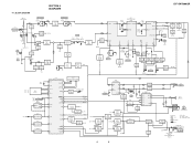
... REG REG 2ND LOCAL Q202 Q202 Q201 Q201 SWITCH SWITCH SWITCH SWITCH Q208 SWITCH Q203 MUTING S201 AM MODE AM REG - BLOCK DIAGRAM SECTION 4 DIAGRAMS ICF-SW7600GR ANT101 (TELESCOPIC) FM TRACKING T101 CT101 FM ANT J101 AM EXT ANT (EXCEPT CH) Q120 ATT VT Q101 MUTING CONTROL MUTING ROD B BAR B S101 ATT... B+ SWITCH • Signal Path : FM : MW/LW • Abbreviation CH: Chinese model EA: Saudi Arabia model : SW BATT EXCEPT CH J203 DC IN 6V DRY BATTERY SIZE"AA" (IEC DESIGNATION R6) 4PCS,6V 9 9 4-1. SSB SYNC NORM -
... REG REG 2ND LOCAL Q202 Q202 Q201 Q201 SWITCH SWITCH SWITCH SWITCH Q208 SWITCH Q203 MUTING S201 AM MODE AM REG - BLOCK DIAGRAM SECTION 4 DIAGRAMS ICF-SW7600GR ANT101 (TELESCOPIC) FM TRACKING T101 CT101 FM ANT J101 AM EXT ANT (EXCEPT CH) Q120 ATT VT Q101 MUTING CONTROL MUTING ROD B BAR B S101 ATT... B+ SWITCH • Signal Path : FM : MW/LW • Abbreviation CH: Chinese model EA: Saudi Arabia model : SW BATT EXCEPT CH J203 DC IN 6V DRY BATTERY SIZE"AA" (IEC DESIGNATION R6) 4PCS,6V 9 9 4-1. SSB SYNC NORM -
Service Manual
Page 10
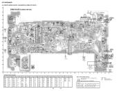
... F-10 Q219 F-11 Q220 F-11 Q221 F-11 Q222 F-12 Q223 F-11 Q224 F-12 Q225 F-12 10 10 SP201 SPEAKER 8Ω K A DRY BATTERY SIZE "AA" (IEC DESIGNATION R6) 4PCS. 6V K A CH A K J203 DC IN 6V 11 1-679-368- (11) 10 11 12 13... D206 F-6 Q105 D-12 Q114 D-12 Q202 C-3 Q211 F-3 D109 E-9 D207 I T203 T203 A TO KEY BOARD 1 2 3 4 5 6 7 8 9 • Semiconductor Location Ref. ICF-SW7600GR 4-2. Location Ref. No. No. Caution: Pattern face side: (Conductor Side) Parts face side: (Component Side) Parts on the parts face side seen from the pattern...
... F-10 Q219 F-11 Q220 F-11 Q221 F-11 Q222 F-12 Q223 F-11 Q224 F-12 Q225 F-12 10 10 SP201 SPEAKER 8Ω K A DRY BATTERY SIZE "AA" (IEC DESIGNATION R6) 4PCS. 6V K A CH A K J203 DC IN 6V 11 1-679-368- (11) 10 11 12 13... D206 F-6 Q105 D-12 Q114 D-12 Q202 C-3 Q211 F-3 D109 E-9 D207 I T203 T203 A TO KEY BOARD 1 2 3 4 5 6 7 8 9 • Semiconductor Location Ref. ICF-SW7600GR 4-2. Location Ref. No. No. Caution: Pattern face side: (Conductor Side) Parts face side: (Component Side) Parts on the parts face side seen from the pattern...
Service Manual
Page 17
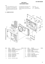
... BUTTON (PAGE) Ref. Description 3-893-852-01 3-918-696-01 3-227-402-01 3-227-403-01 7-685-152-19 CUSHION (BATTERY CASE LID) SCREW (M3X6 LOCK ACE) STAND TERMINAL (+/-), BATTERY SCREW +BTP 3X25 TYPE2 N-S 5 3-227-387-01 SHEET (BUTTON), ADHESIVE 6 3-227-385-01 BUTTON (SCAN) 7 3-227-384... FOOT, RUBBER CABINET (REAR) (EXCEPT CH) CABINET (REAR) (CH) LID, BATTERY CASE ANTENNA, TELESCOPIC 10 3-227-401-01 PLATE (ANT), CONTACT Remarks 17 No. 11 12 13 14 15 Part No. SECTION 5 EXPLODED VIEWS ICF-SW7600GR NOTE: • -XX, -X mean standardized parts, so they may have some differences...
... BUTTON (PAGE) Ref. Description 3-893-852-01 3-918-696-01 3-227-402-01 3-227-403-01 7-685-152-19 CUSHION (BATTERY CASE LID) SCREW (M3X6 LOCK ACE) STAND TERMINAL (+/-), BATTERY SCREW +BTP 3X25 TYPE2 N-S 5 3-227-387-01 SHEET (BUTTON), ADHESIVE 6 3-227-385-01 BUTTON (SCAN) 7 3-227-384... FOOT, RUBBER CABINET (REAR) (EXCEPT CH) CABINET (REAR) (CH) LID, BATTERY CASE ANTENNA, TELESCOPIC 10 3-227-401-01 PLATE (ANT), CONTACT Remarks 17 No. 11 12 13 14 15 Part No. SECTION 5 EXPLODED VIEWS ICF-SW7600GR NOTE: • -XX, -X mean standardized parts, so they may have some differences...
Service Manual
Page 18
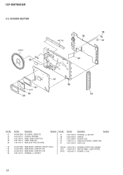
... 58 * 59 * 60 * 61 Part No. ICF-SW7600GR 5-2. CHASSIS SECTION SP201 52 ANT102 56 55 57 54 51 61 LCD1 60 59 58 53 Ref. Description Remarks 3-227-396-01 3-227-392-01 3-227-389-01 1-694-751-11 3-227-390-01 TERMINAL (+), BATTERY CHASSIS HOLDER (LCD) CONDUCTIVE BOARD, CONNECTION CASE (LCD... A-4440-288-A MAIN BOARD, COMPLETE (EXCEPT CH,EA) A-4440-290-A MAIN BOARD, COMPLETE (EA) A-4440-291-A MAIN BOARD, COMPLETE (CH) 3-227-397-01 TERMINAL (-), BATTERY ANT102 1-402-479-21 ANTENNA, FERRITE-ROD (LW/MW) LCD1 1-804-194-11 DISPLAY PANEL, LIQUID CRYSTAL SP201 1-529-942-11 SPEAKER (7.7cm) 18
... 58 * 59 * 60 * 61 Part No. ICF-SW7600GR 5-2. CHASSIS SECTION SP201 52 ANT102 56 55 57 54 51 61 LCD1 60 59 58 53 Ref. Description Remarks 3-227-396-01 3-227-392-01 3-227-389-01 1-694-751-11 3-227-390-01 TERMINAL (+), BATTERY CHASSIS HOLDER (LCD) CONDUCTIVE BOARD, CONNECTION CASE (LCD... A-4440-288-A MAIN BOARD, COMPLETE (EXCEPT CH,EA) A-4440-290-A MAIN BOARD, COMPLETE (EA) A-4440-291-A MAIN BOARD, COMPLETE (CH) 3-227-397-01 TERMINAL (-), BATTERY ANT102 1-402-479-21 ANTENNA, FERRITE-ROD (LW/MW) LCD1 1-804-194-11 DISPLAY PANEL, LIQUID CRYSTAL SP201 1-529-942-11 SPEAKER (7.7cm) 18


