Operating Instructions
Page 1
3-227-586-13 (1) FM Stereo/SW/MW/LW PLL Synthesized Receiver Operating instructions GB Mode d'emploi FR Bedienungsanleitung DE Manual de instrucciones ES Gebruiksaanwijzing NL Manual de Instruções PT ICF-SW7600GR Sony Corporation 2001 Printed in Japan
3-227-586-13 (1) FM Stereo/SW/MW/LW PLL Synthesized Receiver Operating instructions GB Mode d'emploi FR Bedienungsanleitung DE Manual de instrucciones ES Gebruiksaanwijzing NL Manual de Instruções PT ICF-SW7600GR Sony Corporation 2001 Printed in Japan
Operating Instructions
Page 2
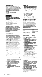
...Memory scan tuning for automatically searching available stations from 60 min., 45 min., 30 min., and 15 min. • Stereo FM reception You can enjoy FM broadcasts in the U.S.A. ICF-SW7600GR Serial No Warning To prevent fire or shock hazard, do not open the cabinet. For the customers in... American countries Other countries MW channel step 10 kHz 9 kHz • Five types tuning methods to suit your Sony dealer regarding this equipment does cause harmful interference to radio or television reception, which the receiver is factory-set to 9 kHz or 10 kHz. Model No. INFORMATION This...
...Memory scan tuning for automatically searching available stations from 60 min., 45 min., 30 min., and 15 min. • Stereo FM reception You can enjoy FM broadcasts in the U.S.A. ICF-SW7600GR Serial No Warning To prevent fire or shock hazard, do not open the cabinet. For the customers in... American countries Other countries MW channel step 10 kHz 9 kHz • Five types tuning methods to suit your Sony dealer regarding this equipment does cause harmful interference to radio or television reception, which the receiver is factory-set to 9 kHz or 10 kHz. Model No. INFORMATION This...
Operating Instructions
Page 4
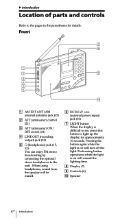
...) 2 ATT (attenuator) control (21) 3 ATT (attenuator) ON/ OFF switch (21) 4 LINE OUT (recording output) jack (33) 5 2 (headphones) jack (17, 33) You can enjoy FM stereo broadcasting by connecting the optional stereo headphones to the unit . B Introduction Location of parts and controls Refer to the pages in the parentheses for approximately 10 seconds.
...) 2 ATT (attenuator) control (21) 3 ATT (attenuator) ON/ OFF switch (21) 4 LINE OUT (recording output) jack (33) 5 2 (headphones) jack (17, 33) You can enjoy FM stereo broadcasting by connecting the optional stereo headphones to the unit . B Introduction Location of parts and controls Refer to the pages in the parentheses for approximately 10 seconds.
Operating Instructions
Page 17
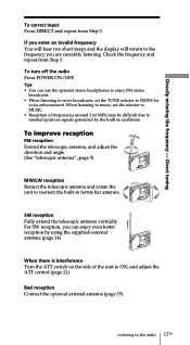
...See "telescopic antenna", page 5) MW/LW reception Retract the telescopic antenna and rotate the unit to the frequency you can use the optional stereo headphones to enjoy FM stereo broadcasts. • When listening to news broadcasts, set the selector to MUSIC. • Reception of frequencies around 3.64 MHz may ... and adjust the ATT control (page 21). For SW reception, you are currently listening. Directly entering the frequency - To turn off the radio Press POWER ON/OFF. Tips • You can enjoy even better reception by the built-in ferrite bar antenna. SW reception Fully extend the...
...See "telescopic antenna", page 5) MW/LW reception Retract the telescopic antenna and rotate the unit to the frequency you can use the optional stereo headphones to enjoy FM stereo broadcasts. • When listening to news broadcasts, set the selector to MUSIC. • Reception of frequencies around 3.64 MHz may ... and adjust the ATT control (page 21). For SW reception, you are currently listening. Directly entering the frequency - To turn off the radio Press POWER ON/OFF. Tips • You can enjoy even better reception by the built-in ferrite bar antenna. SW reception Fully extend the...

Operating Instructions
Page 33
... necessary. 3 Record on the recording. Use the appropriate cable for the type of cassette recorder. Cassette recorder Type Jack Connecting cable (optional) Monaural Stereo MIC IN (minijack) MIC IN (minijack) LINE IN (minijack) LINE IN (pinjack) RK-G135 RK-G134 RK-G136 RK-G129 2 Tune in...channels will be recorded in monaural. To record FM broadcasts in stereo, be recorded in monaural. Otherwise, both channels will be sure to record. to MIC IN or LINE IN Cassette recorder to LINE OUT 1 Connect the radio to a cassette recorder with the optional connecting cable. Hold ...
... necessary. 3 Record on the recording. Use the appropriate cable for the type of cassette recorder. Cassette recorder Type Jack Connecting cable (optional) Monaural Stereo MIC IN (minijack) MIC IN (minijack) LINE IN (minijack) LINE IN (pinjack) RK-G135 RK-G134 RK-G136 RK-G129 2 Tune in...channels will be recorded in monaural. To record FM broadcasts in stereo, be recorded in monaural. Otherwise, both channels will be sure to record. to MIC IN or LINE IN Cassette recorder to LINE OUT 1 Connect the radio to a cassette recorder with the optional connecting cable. Hold ...
Operating Instructions
Page 40
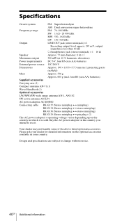
...- 29 999 kHz MW: 530-1 620 kHz LW: 150-529 kHz Output LINE OUT jack (stereo minijack) × 1 Recording output level approx. 245 mV, output impedance less than 10 kΩ i (headphones) jack (stereo minijack) × 1 16 Ω Speaker Approx. 77 mm diameter, 8 Ω ×...-102 SW active antenna AN-LP1 AC power adopter AC-E60HG Connecting cable RK-G135 (Stereo miniplug y miniplug) RK-G134 (Stereo miniplug y stereo miniplug) RK-G136 (Stereo miniplug y stereo miniplug) RK-G129 (Stereo miniplug y pin plug × 2) The AC power adopter's operating voltage varies depending upon...
...- 29 999 kHz MW: 530-1 620 kHz LW: 150-529 kHz Output LINE OUT jack (stereo minijack) × 1 Recording output level approx. 245 mV, output impedance less than 10 kΩ i (headphones) jack (stereo minijack) × 1 16 Ω Speaker Approx. 77 mm diameter, 8 Ω ×...-102 SW active antenna AN-LP1 AC power adopter AC-E60HG Connecting cable RK-G135 (Stereo miniplug y miniplug) RK-G134 (Stereo miniplug y stereo miniplug) RK-G136 (Stereo miniplug y stereo miniplug) RK-G129 (Stereo miniplug y pin plug × 2) The AC power adopter's operating voltage varies depending upon...
Service Manual
Page 1
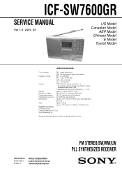
... and specifications are subject to change without notice. 9-873-099-11 2001C1600-1 © 2001.3 Sony Corporation Audio Entertainment Group General Engineering Dept. projecting parts (w/h/d) Mass Approx. 536 g Approx. 608 g (incl. FM STEREO/SW/MW/LW PLL SYNTHESIZED RECEIVER ICF-SW7600GR SERVICE MANUAL Ver 1.0 2001. 03 US Model Canadian Model AEP Model Chinese Model E Model...
... and specifications are subject to change without notice. 9-873-099-11 2001C1600-1 © 2001.3 Sony Corporation Audio Entertainment Group General Engineering Dept. projecting parts (w/h/d) Mass Approx. 536 g Approx. 608 g (incl. FM STEREO/SW/MW/LW PLL SYNTHESIZED RECEIVER ICF-SW7600GR SERVICE MANUAL Ver 1.0 2001. 03 US Model Canadian Model AEP Model Chinese Model E Model...
Service Manual
Page 3
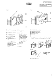
...) 3 ATT (attenuator) ON/ OFF switch (21) 4 LINE OUT (recording output) jack (33) 5 2 (headphones) jack (17, 33) You can enjoy FM stereo broadcasting by connecting the optional stereo headphones to the unit . Front SECTION 1 GENERAL Rear ICF-SW7600GR This section is extracted from the speaker will be sure to push in the base as well.
...) 3 ATT (attenuator) ON/ OFF switch (21) 4 LINE OUT (recording output) jack (33) 5 2 (headphones) jack (17, 33) You can enjoy FM stereo broadcasting by connecting the optional stereo headphones to the unit . Front SECTION 1 GENERAL Rear ICF-SW7600GR This section is extracted from the speaker will be sure to push in the base as well.
Service Manual
Page 9
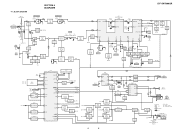
SSB SYNC NORM - BLOCK DIAGRAM SECTION 4 DIAGRAMS ICF-SW7600GR ANT101 (TELESCOPIC) FM TRACKING T101 CT101 FM ANT J101 AM EXT ANT (EXCEPT CH) Q120 ATT VT Q101 MUTING CONTROL MUTING ROD B BAR B S101 ATT ... Q210 SWITCH FM REG AM REG Q211 MUTING MUTING MUTING RV203 76k(MPX) IC202 PLL FM MPX 1 IN L9 4 VCO R 10 NEWS STOP 8 MUSIC Q212 STEREO CONTROL S203 TONE BEEP RV204 VOLUMEw Q214 LINE AMP Q213 LINE AMP IC203 PRE/POWER AMP 1 IN2 L OUT2 7 16 IN1 R 4 NF2 OUT1 10 13 NF1...
SSB SYNC NORM - BLOCK DIAGRAM SECTION 4 DIAGRAMS ICF-SW7600GR ANT101 (TELESCOPIC) FM TRACKING T101 CT101 FM ANT J101 AM EXT ANT (EXCEPT CH) Q120 ATT VT Q101 MUTING CONTROL MUTING ROD B BAR B S101 ATT ... Q210 SWITCH FM REG AM REG Q211 MUTING MUTING MUTING RV203 76k(MPX) IC202 PLL FM MPX 1 IN L9 4 VCO R 10 NEWS STOP 8 MUSIC Q212 STEREO CONTROL S203 TONE BEEP RV204 VOLUMEw Q214 LINE AMP Q213 LINE AMP IC203 PRE/POWER AMP 1 IN2 L OUT2 7 16 IN1 R 4 NF2 OUT1 10 13 NF1...
Service Manual
Page 16
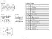
...output I Signal detector signal input I Reception level signal input O Serial clock output for EEPROM I Key input protect switch signal input O Radio power control signal output O AM/FM select signal output O Bar/Rod antenna select signal output - Pin for capacitor connection for oscillation ...RIPPLE IN1 REG VOL NF1 GND1 P-GND1 OUT1 VCC R L M/ST STLED GND NC IN NC NC ICF-SW7600GR • IC BLOCK DIAGRAMS IC201 CXA1376AS IC202 LA3335M 10 9 DECODER 8 SYNC DET 7 6 LAMP TRIGGER STEREO SWITCH FF 90º FF 1/2 FF 0º PHASE COMPALATE V.C.O VCO STOP 1 2 3 4 ...
...output I Signal detector signal input I Reception level signal input O Serial clock output for EEPROM I Key input protect switch signal input O Radio power control signal output O AM/FM select signal output O Bar/Rod antenna select signal output - Pin for capacitor connection for oscillation ...RIPPLE IN1 REG VOL NF1 GND1 P-GND1 OUT1 VCC R L M/ST STLED GND NC IN NC NC ICF-SW7600GR • IC BLOCK DIAGRAMS IC201 CXA1376AS IC202 LA3335M 10 9 DECODER 8 SYNC DET 7 6 LAMP TRIGGER STEREO SWITCH FF 90º FF 1/2 FF 0º PHASE COMPALATE V.C.O VCO STOP 1 2 3 4 ...