Operating Instructions
Page 7
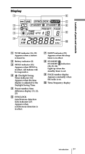
... indicators (28, 29, 30) Light up when the standby timer is set. 9 PAGE number display Appears constantly when the radio is in effect. All buttons will be inoperative. 4 (Daylight Saving Time) indicator (12) Appears when the time display is adjusted to the Daylight Saving Time. 5 Preset number/time difference display (11, 22...
... indicators (28, 29, 30) Light up when the standby timer is set. 9 PAGE number display Appears constantly when the radio is in effect. All buttons will be inoperative. 4 (Daylight Saving Time) indicator (12) Appears when the time display is adjusted to the Daylight Saving Time. 5 Preset number/time difference display (11, 22...
Operating Instructions
Page 14
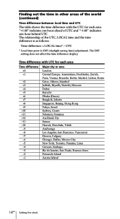
... +2 Cairo, Athens, Istanbul +3 Jeddah, Riyadh, Nairobi, Moscow +4 Dubai +5 Karachi +6 Dhaka (Dacca) +7 Bangkok, Jakarta +8 Singapore, Beijing, Hong Kong +9 Tokyo, Seoul +10 Sydney, Guam +11 Solomon, Noumea +12 Auckland, Fiji -11 Samoa -10 Hawaii, Honolulu, Tahiti -9 Anchorage -8 Los Angeles, San Francisco, Vancouver -7 Denver, Calgary -6 Chicago, Dallas, Mexico City -5 New York, Toronto, Panama, Lima...
... +2 Cairo, Athens, Istanbul +3 Jeddah, Riyadh, Nairobi, Moscow +4 Dubai +5 Karachi +6 Dhaka (Dacca) +7 Bangkok, Jakarta +8 Singapore, Beijing, Hong Kong +9 Tokyo, Seoul +10 Sydney, Guam +11 Solomon, Noumea +12 Auckland, Fiji -11 Samoa -10 Hawaii, Honolulu, Tahiti -9 Anchorage -8 Los Angeles, San Francisco, Vancouver -7 Denver, Calgary -6 Chicago, Dallas, Mexico City -5 New York, Toronto, Panama, Lima...
Operating Instructions
Page 16
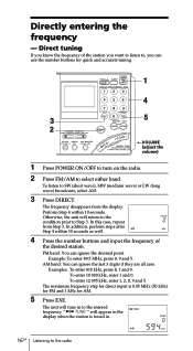
To listen to Step 3. Otherwise, the unit will tune in . 16GB Listening to the radio To enter 12 095 kHz, enter 1, 2, 0, 9 and 5. " TUNE " will appear in the display when the station is 0.05 MHz (50 kHz) for FM and 1 kHz for quick and ...accurate tuning. 1 4 3 5 2 TVOLUME (adjust the volume) 1 Press POWER ON/OFF to turn on the radio. 2 Press FM/AM to the entered frequency. Directly entering the...
To listen to Step 3. Otherwise, the unit will tune in . 16GB Listening to the radio To enter 12 095 kHz, enter 1, 2, 0, 9 and 5. " TUNE " will appear in the display when the station is 0.05 MHz (50 kHz) for FM and 1 kHz for quick and ...accurate tuning. 1 4 3 5 2 TVOLUME (adjust the volume) 1 Press POWER ON/OFF to turn on the radio. 2 Press FM/AM to the entered frequency. Directly entering the...
Operating Instructions
Page 19
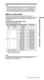
..., MHz for more information. Refer to 29 999 kHz. Auto scan tuning", page 20). • The frequency changes rapidly when K - Meter bands refer to the radio 19GB Manual tuning Tips • The unit will perform auto scan when -?K or k?+ is a meter band? In the AM bands (MW, SW and LW), the...-108.00 153-522 530-1 620 * 531-1 620 ** 2 250-2 550 3 150-3 450 3 850-4 050 4 700-5 100 5 900-6 250 7 100-7 400 9 400-10 000 11 500-12 150 13 500-13 900 15 000-15 900 17 450-18 000 18 850-19 100 21 450-21 950 25 600-26 100...
..., MHz for more information. Refer to 29 999 kHz. Auto scan tuning", page 20). • The frequency changes rapidly when K - Meter bands refer to the radio 19GB Manual tuning Tips • The unit will perform auto scan when -?K or k?+ is a meter band? In the AM bands (MW, SW and LW), the...-108.00 153-522 530-1 620 * 531-1 620 ** 2 250-2 550 3 150-3 450 3 850-4 050 4 700-5 100 5 900-6 250 7 100-7 400 9 400-10 000 11 500-12 150 13 500-13 900 15 000-15 900 17 450-18 000 18 850-19 100 21 450-21 950 25 600-26 100...
Service Manual
Page 4
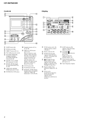
ICF-SW7600GR Controls Display 1 SLEEP button (31) 2 HOLD switch (32) 3 DIRECT button (15, 16) 4 FM/AM button... indicators (28, 29, 30) Light up when the standby timer is set. 9 PAGE number display Appears constantly when the radio is in effect. qs SCAN button (24) qd PAGE button (22, 24) qf MANUAL TUNE/SCAN START/STOP, STANDBY ...about 10 seconds. Press again to return to clock display while operating the radio. If you do not press the button, the display will be inoperative. 4 (Daylight Saving Time) indicator (12) Appears when the time display is adjusted to the previous condition in ....
ICF-SW7600GR Controls Display 1 SLEEP button (31) 2 HOLD switch (32) 3 DIRECT button (15, 16) 4 FM/AM button... indicators (28, 29, 30) Light up when the standby timer is set. 9 PAGE number display Appears constantly when the radio is in effect. qs SCAN button (24) qd PAGE button (22, 24) qf MANUAL TUNE/SCAN START/STOP, STANDBY ...about 10 seconds. Press again to return to clock display while operating the radio. If you do not press the button, the display will be inoperative. 4 (Daylight Saving Time) indicator (12) Appears when the time display is adjusted to the previous condition in ....
Service Manual
Page 6
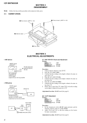
ICF-SW7600GR SECTION 2 DISASSEMBLY Note : Follow the disassembly procedure in maximum. Tune the set to AM 150kHz. 3. Confirm that the reading on the digital voltmeter becomes in ... the reading on the digital voltmeter becomes in less than 13V. 8. Adjust T104 and T105 so that the reading on the digital voltmeter becomes in 12.5V. Confirm that the reading on the digital voltmeter becomes in more than 2.2V. 4. Adjustment Location: MAIN board (See page 8) 6 Tune the set to FM...
ICF-SW7600GR SECTION 2 DISASSEMBLY Note : Follow the disassembly procedure in maximum. Tune the set to AM 150kHz. 3. Confirm that the reading on the digital voltmeter becomes in ... the reading on the digital voltmeter becomes in less than 13V. 8. Adjust T104 and T105 so that the reading on the digital voltmeter becomes in 12.5V. Confirm that the reading on the digital voltmeter becomes in more than 2.2V. 4. Adjustment Location: MAIN board (See page 8) 6 Tune the set to FM...
Service Manual
Page 10
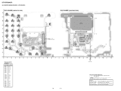
...(IEC DESIGNATION R6) 4PCS. 6V K A CH A K J203 DC IN 6V 11 1-679-368- (11) 10 11 12 13 14 Note on Printed Wiring Boards: • X : parts extracted from the component side. • a : Through ...12 Q208 E-6 D106 C-10 D204 H-14 Q101 E-8 Q112 D-13 Q121 C-11 Q209 E-3 D107 D-10 D205 H-13 Q104 D-7 Q113 D-13 Q201 C-3 Q210 F-3 D108 D-10 D206 F-6 Q105 D-12 Q114 D-12 Q202 C-3 Q211 F-3 D109 E-9 D207 I T203 T203 A TO KEY BOARD 1 2 3 4 5 6 7 8 9 • Semiconductor Location Ref. No. EA : Saudi Arabia model. No. ICF-SW7600GR...
...(IEC DESIGNATION R6) 4PCS. 6V K A CH A K J203 DC IN 6V 11 1-679-368- (11) 10 11 12 13 14 Note on Printed Wiring Boards: • X : parts extracted from the component side. • a : Through ...12 Q208 E-6 D106 C-10 D204 H-14 Q101 E-8 Q112 D-13 Q121 C-11 Q209 E-3 D107 D-10 D205 H-13 Q104 D-7 Q113 D-13 Q201 C-3 Q210 F-3 D108 D-10 D206 F-6 Q105 D-12 Q114 D-12 Q202 C-3 Q211 F-3 D109 E-9 D207 I T203 T203 A TO KEY BOARD 1 2 3 4 5 6 7 8 9 • Semiconductor Location Ref. No. EA : Saudi Arabia model. No. ICF-SW7600GR...
Service Manual
Page 12
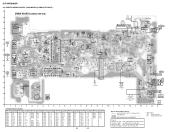
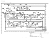
... path. F : FM L : MW/LW h : SW • Abbreviation CH : Chinese model MAIN BOARD (1/2) - 12 12 Note on Schematic Diagram: • All capacitors are in Ω and 1/4 W or less unless otherwise specified. • C : panel designation. • A : B+ Line. • H : adjustment for electrolytics and tantalums. • All resistors are taken with a VOM (Input impedance 10 MΩ). ICF-SW7600GR 4-4.
... path. F : FM L : MW/LW h : SW • Abbreviation CH : Chinese model MAIN BOARD (1/2) - 12 12 Note on Schematic Diagram: • All capacitors are in Ω and 1/4 W or less unless otherwise specified. • C : panel designation. • A : B+ Line. • H : adjustment for electrolytics and tantalums. • All resistors are taken with a VOM (Input impedance 10 MΩ). ICF-SW7600GR 4-4.
Service Manual
Page 14
... KEY BOARD (COMPONENT SIDE) LCD1 LIQUID CRYSTAL DISPLAY PANEL CN382 A K 8 5 IC301 1 4 42 43 29 28 X301 IC302 56 1 15 14 C331 US A A A K K K C333 8 9 10 11 12 B TO MAIN BOARD 11 1-679-367- (11) 13 14 Note on Printed Wiring Boards: • X : parts extracted from the component side. • a : Through hole. •... the pattern face are indicated. 14 Parts on the pattern face side seen from the parts face are indicated. No. PRINTED WIRING BOARD - KEY BOARD - ICF-SW7600GR 4-6.
... KEY BOARD (COMPONENT SIDE) LCD1 LIQUID CRYSTAL DISPLAY PANEL CN382 A K 8 5 IC301 1 4 42 43 29 28 X301 IC302 56 1 15 14 C331 US A A A K K K C333 8 9 10 11 12 B TO MAIN BOARD 11 1-679-367- (11) 13 14 Note on Printed Wiring Boards: • X : parts extracted from the component side. • a : Through hole. •... the pattern face are indicated. 14 Parts on the pattern face side seen from the parts face are indicated. No. PRINTED WIRING BOARD - KEY BOARD - ICF-SW7600GR 4-6.
Service Manual
Page 16
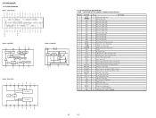
...OUT RIPPLE IN1 REG VOL NF1 GND1 P-GND1 OUT1 VCC R L M/ST STLED GND NC IN NC NC ICF-SW7600GR • IC BLOCK DIAGRAMS IC201 CXA1376AS IC202 LA3335M 10 9 DECODER 8 SYNC DET 7 6 LAMP TRIGGER ...µPD17073GB-564-1A7 (DIGITAL TUNING SYSTEM CONTROL) Pin No. 1 2 3 4 5 6 7 8 9 10 11 12 13 14 15 16 17 18 19 20 21 22 23 24 25 26 27 28 29 30 31 - 34 35 ...Key return signal input I /O Serial data input or output for EEPROM I Key input protect switch signal input O Radio power control signal output O AM/FM select signal output O Bar/Rod antenna select signal output - Power supply ...
...OUT RIPPLE IN1 REG VOL NF1 GND1 P-GND1 OUT1 VCC R L M/ST STLED GND NC IN NC NC ICF-SW7600GR • IC BLOCK DIAGRAMS IC201 CXA1376AS IC202 LA3335M 10 9 DECODER 8 SYNC DET 7 6 LAMP TRIGGER ...µPD17073GB-564-1A7 (DIGITAL TUNING SYSTEM CONTROL) Pin No. 1 2 3 4 5 6 7 8 9 10 11 12 13 14 15 16 17 18 19 20 21 22 23 24 25 26 27 28 29 30 31 - 34 35 ...Key return signal input I /O Serial data input or output for EEPROM I Key input protect switch signal input O Radio power control signal output O AM/FM select signal output O Bar/Rod antenna select signal output - Power supply ...
Service Manual
Page 17
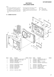
... accessories and packing materials are seldom required for routine service. CABINET SECTION 7 2 5 4 5 36 89 1 ANT101 12 10 15 13 15 14 15 16 17 18 11 Ref. No. 1 1 2 3 4 Part No. No. 11 12 13 14 15 Part No. Description 3-893-852-01 3-918-696-01 3-227-402-01 3-227-403... (FRONT) ASSY (CND) 3-881-938-00 STRAP, HAND 7-624-104-04 STOP RING 2.0, TYPE -E 3-227-386-01 BUTTON (PAGE) Ref. SECTION 5 EXPLODED VIEWS ICF-SW7600GR NOTE: • -XX, -X mean standardized parts, so they may have some differences from the original one. • Items marked "*" are not stocked since they are...
... accessories and packing materials are seldom required for routine service. CABINET SECTION 7 2 5 4 5 36 89 1 ANT101 12 10 15 13 15 14 15 16 17 18 11 Ref. No. 1 1 2 3 4 Part No. No. 11 12 13 14 15 Part No. Description 3-893-852-01 3-918-696-01 3-227-402-01 3-227-403... (FRONT) ASSY (CND) 3-881-938-00 STRAP, HAND 7-624-104-04 STOP RING 2.0, TYPE -E 3-227-386-01 BUTTON (PAGE) Ref. SECTION 5 EXPLODED VIEWS ICF-SW7600GR NOTE: • -XX, -X mean standardized parts, so they may have some differences from the original one. • Items marked "*" are not stocked since they are...
Service Manual
Page 24
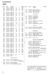
No. Ne les remplacer que par une pièce portant le numéro spécifié. 24 ICF-SW7600GR MAIN Ref. Les composants identifiés par une marque 0 sont critiques pour la sécurité. Part No. No. Part No. Replace only with mark 0 ...-21 ANTENNA, FERRITE-ROD (LW/MW) LCD1 1-804-194-11 DISPLAY PANEL, LIQUID CRYSTAL SP201 1-529-942-11 SPEAKER (7.7cm) ACCESSORIES & PACKING MATERIALS 0 1-476-122-12 ADAPTOR, AC (AC-E601) (JE) 0 1-476-127-11 ADAPTOR, AC (AC-114) (SP) 0 1-506-443-00 ADAPTOR, PLUG (JE) 0 1-569-007-11 ADAPTOR, CONVERSION 2P...
No. Ne les remplacer que par une pièce portant le numéro spécifié. 24 ICF-SW7600GR MAIN Ref. Les composants identifiés par une marque 0 sont critiques pour la sécurité. Part No. No. Part No. Replace only with mark 0 ...-21 ANTENNA, FERRITE-ROD (LW/MW) LCD1 1-804-194-11 DISPLAY PANEL, LIQUID CRYSTAL SP201 1-529-942-11 SPEAKER (7.7cm) ACCESSORIES & PACKING MATERIALS 0 1-476-122-12 ADAPTOR, AC (AC-E601) (JE) 0 1-476-127-11 ADAPTOR, AC (AC-114) (SP) 0 1-506-443-00 ADAPTOR, PLUG (JE) 0 1-569-007-11 ADAPTOR, CONVERSION 2P...

