Operating Instructions
Page 4
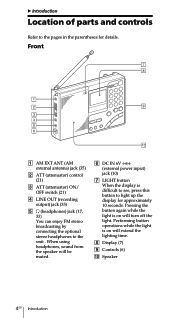
... will extend the lighting time. 8 Display (7) 9 Controls (6) 0 Speaker 4GB Introduction Front 1 AM EXT ANT (AM external antenna) jack (35) 2 ATT (attenuator) control (21) 3 ATT (attenuator) ON/ OFF switch (21) 4 LINE OUT (recording output) jack (33) 5 2 (headphones) jack (17, 33) You can enjoy FM stereo broadcasting by connecting the optional stereo headphones to light up...
... will extend the lighting time. 8 Display (7) 9 Controls (6) 0 Speaker 4GB Introduction Front 1 AM EXT ANT (AM external antenna) jack (35) 2 ATT (attenuator) control (21) 3 ATT (attenuator) ON/ OFF switch (21) 4 LINE OUT (recording output) jack (33) 5 2 (headphones) jack (17, 33) You can enjoy FM stereo broadcasting by connecting the optional stereo headphones to light up...
Operating Instructions
Page 35
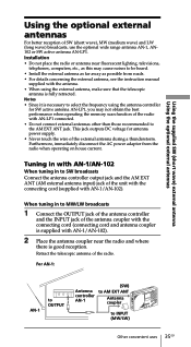
... reception. For AN-1: AN-1 to OUTPUT Antenna controller AN-1 (SW) to AM EXT ANT Antenna coupler to SW broadcasts Connect the antenna controller output jack and the AM EXT ANT (AM external antenna input) jack of the external antenna during a thunderstorm. Installation • Do not place the radio or antenna near the radio and where there is necessary to select...
... reception. For AN-1: AN-1 to OUTPUT Antenna controller AN-1 (SW) to AM EXT ANT Antenna coupler to SW broadcasts Connect the antenna controller output jack and the AM EXT ANT (AM external antenna input) jack of the external antenna during a thunderstorm. Installation • Do not place the radio or antenna near the radio and where there is necessary to select...
Operating Instructions
Page 36
... there is used for this range, the display may change very slowly. Make sure that no liquid or foreign material enters the DC IN 6V jack of 0°C to 40°C (32°F to its recommended temperature range once again. • Reception may be used in its normal condition when...or chemical solvents, as they may mar the casing. • Since a strong magnet is used for the speaker, keep personal credit cards using the external antenna, disconnect the AC power adaptor immediately from the unit to be difficult or noisy in vehicles or buildings. The unit will return to 104°...
... there is used for this range, the display may change very slowly. Make sure that no liquid or foreign material enters the DC IN 6V jack of 0°C to 40°C (32°F to its recommended temperature range once again. • Reception may be used in its normal condition when...or chemical solvents, as they may mar the casing. • Since a strong magnet is used for the speaker, keep personal credit cards using the external antenna, disconnect the AC power adaptor immediately from the unit to be difficult or noisy in vehicles or buildings. The unit will return to 104°...
Operating Instructions
Page 40
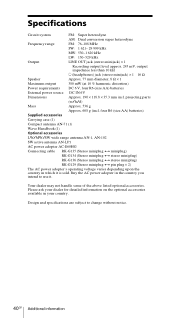
four R6 (size AA) batteries) Supplied accessories Carrying case (1) Compact antenna AN-71 (1) Wave Handbook (1) Optional accessories LW/MW/SW wide range antenna AN-1, AN-102 SW active antenna AN-LP1 AC power adopter AC-E60HG Connecting cable RK-G135 (Stereo miniplug y miniplug) RK-G134 (Stereo ...: 1 621- 29 999 kHz MW: 530-1 620 kHz LW: 150-529 kHz Output LINE OUT jack (stereo minijack) × 1 Recording output level approx. 245 mV, output impedance less than 10 kΩ i (headphones) jack (stereo minijack) × 1 16 Ω Speaker Approx. 77 mm diameter, 8 Ω ...
four R6 (size AA) batteries) Supplied accessories Carrying case (1) Compact antenna AN-71 (1) Wave Handbook (1) Optional accessories LW/MW/SW wide range antenna AN-1, AN-102 SW active antenna AN-LP1 AC power adopter AC-E60HG Connecting cable RK-G135 (Stereo miniplug y miniplug) RK-G134 (Stereo ...: 1 621- 29 999 kHz MW: 530-1 620 kHz LW: 150-529 kHz Output LINE OUT jack (stereo minijack) × 1 Recording output level approx. 245 mV, output impedance less than 10 kΩ i (headphones) jack (stereo minijack) × 1 16 Ω Speaker Approx. 77 mm diameter, 8 Ω ...
Service Manual
Page 1
...batteries) Supplied accessories Carrying case (1) Compact antenna AN-71 (1) Wave Handbook (1) Design and specifications are subject to change without notice. 9-873-099-11 2001C1600-1 © 2001.3 Sony Corporation Audio Entertainment Group General Engineering Dept. ICF-SW7600GR SERVICE MANUAL Ver 1.0 2001. 03 ...- 29 999 kHz MW: 530-1 620 kHz LW: 150-529 kHz Output LINE OUT jack (stereo minijack) × 1 Recording output level approx. 245 mV, output impedance less than 10 kΩ i (headphones) jack (stereo minijack) × 1 16 Ω Speaker Approx. 77 mm diameter, 8 ...
...batteries) Supplied accessories Carrying case (1) Compact antenna AN-71 (1) Wave Handbook (1) Design and specifications are subject to change without notice. 9-873-099-11 2001C1600-1 © 2001.3 Sony Corporation Audio Entertainment Group General Engineering Dept. ICF-SW7600GR SERVICE MANUAL Ver 1.0 2001. 03 ...- 29 999 kHz MW: 530-1 620 kHz LW: 150-529 kHz Output LINE OUT jack (stereo minijack) × 1 Recording output level approx. 245 mV, output impedance less than 10 kΩ i (headphones) jack (stereo minijack) × 1 16 Ω Speaker Approx. 77 mm diameter, 8 ...
Service Manual
Page 3
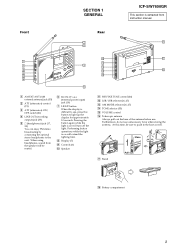
... qk Battery compartment 3 Furthermore, do not use . Front SECTION 1 GENERAL Rear ICF-SW7600GR This section is on will turn off the light. When using headphones, sound from instruction manual. 1 AM EXT ANT (AM external antenna) jack (35) 2 ATT (attenuator) control (21) 3 ATT (attenuator) ON/ OFF... switch (21) 4 LINE OUT (recording output) jack (33) 5 2 (headphones) jack (17, 33) You can enjoy FM stereo broadcasting by connecting the ...
... qk Battery compartment 3 Furthermore, do not use . Front SECTION 1 GENERAL Rear ICF-SW7600GR This section is on will turn off the light. When using headphones, sound from instruction manual. 1 AM EXT ANT (AM external antenna) jack (35) 2 ATT (attenuator) control (21) 3 ATT (attenuator) ON/ OFF... switch (21) 4 LINE OUT (recording output) jack (33) 5 2 (headphones) jack (17, 33) You can enjoy FM stereo broadcasting by connecting the ...
Service Manual
Page 6
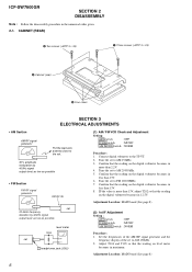
...frequencies of the AM RF signal generator and the frequency display of the set i headphones jack (J202) (1) AM / FM VCO Check and Adjustment Setting: ATT switch : OFF ...switch : NORM Procedure: 1. Connect digital voltmeter to AM 150kHz. 3. IF the value is more than 13V. 8. ICF-SW7600GR SECTION 2 DISASSEMBLY Note : Follow the disassembly procedure in 12.5V. CABINET (REAR) 2 Two screws (+BTP 3... SECTION 3 ELECTRICAL ADJUSTMENTS • AM Section AM RF signal generator Put the lead-wire antenna close to the set. 30% amplitude modulation by 400Hz signal output level: as low as...
...frequencies of the AM RF signal generator and the frequency display of the set i headphones jack (J202) (1) AM / FM VCO Check and Adjustment Setting: ATT switch : OFF ...switch : NORM Procedure: 1. Connect digital voltmeter to AM 150kHz. 3. IF the value is more than 13V. 8. ICF-SW7600GR SECTION 2 DISASSEMBLY Note : Follow the disassembly procedure in 12.5V. CABINET (REAR) 2 Two screws (+BTP 3... SECTION 3 ELECTRICAL ADJUSTMENTS • AM Section AM RF signal generator Put the lead-wire antenna close to the set. 30% amplitude modulation by 400Hz signal output level: as low as...


