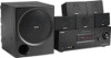
Operating Instructions
Page 2
... and, if not installed and used in particular, specifies that may cause harmful interference to persons. Reorient or relocate the receiving antenna. - Note to CATV system installer: This reminder is intended to alert the user to the presence of uninsulated "dangerous voltage" within the product's enclosure...fire or electric shock, do not expose this equipment. If this equipment does cause harmful interference to radio or television reception, which the receiver is intended to alert the user to correct the interference by one or more of the following measures: - And don't place lighted...
... and, if not installed and used in particular, specifies that may cause harmful interference to persons. Reorient or relocate the receiving antenna. - Note to CATV system installer: This reminder is intended to alert the user to the presence of uninsulated "dangerous voltage" within the product's enclosure...fire or electric shock, do not expose this equipment. If this equipment does cause harmful interference to radio or television reception, which the receiver is intended to alert the user to correct the interference by one or more of the following measures: - And don't place lighted...
Operating Instructions
Page 3
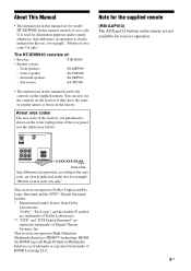
... - "Dolby", "Pro Logic", and the double-D symbol are trademarks of Dolby Laboratories. ** "DTS" and "DTS Digital Surround" are registered trademarks of : • Receiver STR-K900 • Speaker system - Note for model HT-DDW900. HDMI, the HDMI logo and High-Definition Multimedia Interface are for the supplied remote (RM-AAP013) The AUX and 12 buttons on...
... - "Dolby", "Pro Logic", and the double-D symbol are trademarks of Dolby Laboratories. ** "DTS" and "DTS Digital Surround" are registered trademarks of : • Receiver STR-K900 • Speaker system - Note for model HT-DDW900. HDMI, the HDMI logo and High-Definition Multimedia Interface are for the supplied remote (RM-AAP013) The AUX and 12 buttons on...

Operating Instructions
Page 4
... the audio components.........17 3b: Connecting the video components ........20 4: Connecting the antennas 27 5: Preparing the receiver and the remote .....28 6: Selecting the speaker system 29 7: Calibrating the appropriate settings automatically (AUTO CALIBRATION 30 8: Adjusting the speaker levels and balance (TEST TONE 33 Playback Selecting a component 34 Listening/Watching a component 36 Amplifier Operations Navigating...
... the audio components.........17 3b: Connecting the video components ........20 4: Connecting the antennas 27 5: Preparing the receiver and the remote .....28 6: Selecting the speaker system 29 7: Calibrating the appropriate settings automatically (AUTO CALIBRATION 30 8: Adjusting the speaker levels and balance (TEST TONE 33 Playback Selecting a component 34 Listening/Watching a component 36 Amplifier Operations Navigating...

Operating Instructions
Page 5
MOVIE MUSIC MULTI CH IN MUTING qh qg qf qd qs qa q; 98 PUSH To remove the cover Press PUSH. The current status of the selected component or a list of parts Receiver Front Panel 12 3 4 56 7 ?/1 SPEAKERS (OFF/A/B/A+B) AUTO CAL MIC PHONES VIDEO 3 IN... ENTER MODE TUNING 2CH A.F.D. Press to turn the receiver on or off (page 28, 36, 37, 52, 71). continued 5US Receives signals from children. Getting Started Getting Started Description and location of selectable items appears here (page 7). Name A ?/1 B SPEAKERS (OFF/A/B/A+B) C Display D Remote sensor Function Press...
MOVIE MUSIC MULTI CH IN MUTING qh qg qf qd qs qa q; 98 PUSH To remove the cover Press PUSH. The current status of the selected component or a list of parts Receiver Front Panel 12 3 4 56 7 ?/1 SPEAKERS (OFF/A/B/A+B) AUTO CAL MIC PHONES VIDEO 3 IN... ENTER MODE TUNING 2CH A.F.D. Press to turn the receiver on or off (page 28, 36, 37, 52, 71). continued 5US Receives signals from children. Getting Started Getting Started Description and location of selectable items appears here (page 7). Name A ?/1 B SPEAKERS (OFF/A/B/A+B) C Display D Remote sensor Function Press...

Operating Instructions
Page 7
...Lights up when the disc being played back contains an LFE (Low Frequency Effect) channel and the LFE channel signal is set to the speaker system used. Lights up when INPUT MODE is set to "AUTO" and the source signal is a digital signal being input through the OPTICAL jack... qa qg MEMORY D.RANGE STEREO MONO q; 9 8 Name A SW B LFE C SP A/SP B D ;DIGITAL E ;PRO LOGIC (II) Function Lights up when using the receiver to "OPT IN" (page 56). "; Lights up when the audio signal is activated. However, these indicators do not function for DTS format signals. continued 7US...
...Lights up when the disc being played back contains an LFE (Low Frequency Effect) channel and the LFE channel signal is set to the speaker system used. Lights up when INPUT MODE is set to "AUTO" and the source signal is a digital signal being input through the OPTICAL jack... qa qg MEMORY D.RANGE STEREO MONO q; 9 8 Name A SW B LFE C SP A/SP B D ;DIGITAL E ;PRO LOGIC (II) Function Lights up when using the receiver to "OPT IN" (page 56). "; Lights up when the audio signal is activated. However, these indicators do not function for DTS format signals. continued 7US...

Operating Instructions
Page 8
Front Left Front Right Center (monaural) Surround Left Surround Right Surround (monaural or the surround components obtained by Pro Logic processing) Example: Recording format (Front/ Surround): 3/2.1 Sound Field: A.F.D. AUTO SW LCR SL SR 8US Name N SLEEP O Playback channel indicators L R C SL SR S Function Lights up when the sleep timer is activated (page 60). The letters (L, C, R, etc.) indicate the channels being played back. The boxes around the letters vary to show how the receiver downmixes the source sound.
Front Left Front Right Center (monaural) Surround Left Surround Right Surround (monaural or the surround components obtained by Pro Logic processing) Example: Recording format (Front/ Surround): 3/2.1 Sound Field: A.F.D. AUTO SW LCR SL SR 8US Name N SLEEP O Playback channel indicators L R C SL SR S Function Lights up when the sleep timer is activated (page 60). The letters (L, C, R, etc.) indicate the channels being played back. The boxes around the letters vary to show how the receiver downmixes the source sound.

Operating Instructions
Page 10
... SLEEP VIDEO1 VIDEO2 VIDEO3 DVD 1 AV ?/1 (on/standby) switch 2 ?/1 (on or off the receiver and other components (SYSTEM STANDBY). MOVIE MUSIC 1 2 3 DUAL FM MONO MODE 4 5 6 AUDIO ANGLE JUMP/ PRESET/ TUNING TIME CH/D.SKIP 7 8 9 MEMORY SUBTITLE ENTER .> 0/10 >10/11 12 D.TUNING DISC ALT mM - White (L) ... channel sound (page 18). ql qk qj 2CH A.F.D. You can use the supplied remote RM-AAP013 to operate the receiver and to control the Sony audio/video components that the remote is assigned to operate. If you press the input buttons (wj). For details, ...
... SLEEP VIDEO1 VIDEO2 VIDEO3 DVD 1 AV ?/1 (on/standby) switch 2 ?/1 (on or off the receiver and other components (SYSTEM STANDBY). MOVIE MUSIC 1 2 3 DUAL FM MONO MODE 4 5 6 AUDIO ANGLE JUMP/ PRESET/ TUNING TIME CH/D.SKIP 7 8 9 MEMORY SUBTITLE ENTER .> 0/10 >10/11 12 D.TUNING DISC ALT mM - White (L) ... channel sound (page 18). ql qk qj 2CH A.F.D. You can use the supplied remote RM-AAP013 to operate the receiver and to control the Sony audio/video components that the remote is assigned to operate. If you press the input buttons (wj). For details, ...

Operating Instructions
Page 11
... recorder, hard disc recorder, PSX, or satellite tuner is displayed on the TV screen of the DVD player. To turn the receiver on or off all speakers at the same time (SYSTEM STANDBY). Press ALT (G) and then press SLEEP to stop playback of all components, press ?/1 and AV ?/1 (A) at the ... TV, VCR, satellite tuner, Blue-ray disc recorder, or hard disc recorder. - L AMP MENU M TV/VIDEO N AUTO CAL O WIDE P TV CH +a)/- Press to the MULTI CH IN jacks. Press to perform menu operations. Q TV VOL +a)/- Then, use the control buttons to adjust the volume level of the VCR, CD...
... recorder, hard disc recorder, PSX, or satellite tuner is displayed on the TV screen of the DVD player. To turn the receiver on or off all speakers at the same time (SYSTEM STANDBY). Press ALT (G) and then press SLEEP to stop playback of all components, press ?/1 and AV ?/1 (A) at the ... TV, VCR, satellite tuner, Blue-ray disc recorder, or hard disc recorder. - L AMP MENU M TV/VIDEO N AUTO CAL O WIDE P TV CH +a)/- Press to the MULTI CH IN jacks. Press to perform menu operations. Q TV VOL +a)/- Then, use the control buttons to adjust the volume level of the VCR, CD...

Operating Instructions
Page 13
...press the numeric buttons to - select track numbers of the TV, VCR, satellite tuner, Blu-ray disc recorder, hard disc recorder, or PSX. Button Assigned Sony component VIDEO1 VCR (VTR mode 3) VIDEO2 VCR (VTR mode 1) VIDEO3 VCR (VTR mode 2) DVD DVD player MD/TAPE MD deck SA-CD/CD Super... wj Input buttons Press one of the buttons to select the component you press any of the input buttons, the receiver turns on page 61. a) The MASTER VOL +, TV VOL +, TV CH + and H buttons have tactile dots. Getting Started Name ANGLE JUMP/TIME MEMORY SUBTITLE ENTER Numeric buttons >10/11 ...
...press the numeric buttons to - select track numbers of the TV, VCR, satellite tuner, Blu-ray disc recorder, hard disc recorder, or PSX. Button Assigned Sony component VIDEO1 VCR (VTR mode 3) VIDEO2 VCR (VTR mode 1) VIDEO3 VCR (VTR mode 2) DVD DVD player MD/TAPE MD deck SA-CD/CD Super... wj Input buttons Press one of the buttons to select the component you press any of the input buttons, the receiver turns on page 61. a) The MASTER VOL +, TV VOL +, TV CH + and H buttons have tactile dots. Getting Started Name ANGLE JUMP/TIME MEMORY SUBTITLE ENTER Numeric buttons >10/11 ...

Operating Instructions
Page 14
...). Example of a 5.1 channel speaker system configuration Installing the speakers on the speaker stand For greater flexibility in positioning the speakers, use a 5.1 channel system (5 speakers and one sub woofer). To fully enjoy theater-like multi channel surround sound requires five speakers (two front speakers, a center speaker, and two surround speakers) and a sub woofer (5.1 channel). AFront speaker (L) BFront speaker (R) CCenter speaker DSurround speaker (L) ESurround speaker (R) FSub woofer Tip...
...). Example of a 5.1 channel speaker system configuration Installing the speakers on the speaker stand For greater flexibility in positioning the speakers, use a 5.1 channel system (5 speakers and one sub woofer). To fully enjoy theater-like multi channel surround sound requires five speakers (two front speakers, a center speaker, and two surround speakers) and a sub woofer (5.1 channel). AFront speaker (L) BFront speaker (R) CCenter speaker DSurround speaker (L) ESurround speaker (R) FSub woofer Tip...

Operating Instructions
Page 17
... below for the pages which describe how to output audio decoded by the component's internal multi-channel decoder through this receiver. This connection is used to connect each component. Select the connection according to "4: Connecting the antennas" (page 27). b)Model ...equipped only with MULTI CH OUTPUT jacks, etc. After hooking up your components. Component to this receiver. Digital Analog L CENTER R SUB FRONT SURROUND WOOFER MULTI CH IN High quality sound 17US Getting Started 3a: Connecting the audio components ...
... below for the pages which describe how to output audio decoded by the component's internal multi-channel decoder through this receiver. This connection is used to connect each component. Select the connection according to "4: Connecting the antennas" (page 27). b)Model ...equipped only with MULTI CH OUTPUT jacks, etc. After hooking up your components. Component to this receiver. Digital Analog L CENTER R SUB FRONT SURROUND WOOFER MULTI CH IN High quality sound 17US Getting Started 3a: Connecting the audio components ...

Operating Instructions
Page 18
...L L L AUDIO CENTER OUT R R AUDIO IN AUDIO IN AUDIO OUT AUDIO IN DVD VIDEO 2 VIDEO 1 R SUB FRONT SURROUND WOOFER SUB MULTI CH IN WOOFER CENTER + - R SURROUND SPEAKERS R FRONT A A Audio cord (not supplied) B Monaural audio cord (not supplied) 18US Connecting components with multi channel output jacks If your DVD or... jacks, you will need to adjust the level of this receiver to enjoy multi channel sound. Note When you make connections to the MULTI CH IN jacks, you can be used to the MULTI CH IN jacks of the speakers and sub woofer using the controls on the connected component...
...L L L AUDIO CENTER OUT R R AUDIO IN AUDIO IN AUDIO OUT AUDIO IN DVD VIDEO 2 VIDEO 1 R SUB FRONT SURROUND WOOFER SUB MULTI CH IN WOOFER CENTER + - R SURROUND SPEAKERS R FRONT A A Audio cord (not supplied) B Monaural audio cord (not supplied) 18US Connecting components with multi channel output jacks If your DVD or... jacks, you will need to adjust the level of this receiver to enjoy multi channel sound. Note When you make connections to the MULTI CH IN jacks, you can be used to the MULTI CH IN jacks of the speakers and sub woofer using the controls on the connected component...
Operating Instructions
Page 20
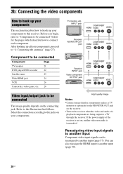
... to be reassigned to another input (page 57). If the power supply of a playback component are being output to a TV through the receiver. You can also reassign the HDMI input to another input Component video input signals can be connected The image quality depends on the connecting jack...; Connect image display components such as a TV monitor or a projector to the MONITOR OUT jack on the receiver. • Turn on the receiver when the video and audio of the receiver is transmitted. 3b: Connecting the video components How to hook up your components This section describes how to hook...
... to be reassigned to another input (page 57). If the power supply of a playback component are being output to a TV through the receiver. You can also reassign the HDMI input to another input Component video input signals can be connected The image quality depends on the connecting jack...; Connect image display components such as a TV monitor or a projector to the MONITOR OUT jack on the receiver. • Turn on the receiver when the video and audio of the receiver is transmitted. 3b: Connecting the video components How to hook up your components This section describes how to hook...

Operating Instructions
Page 21
...L L AUDIO CENTER OUT R R AUDIO IN AUDIO IN AUDIO OUT AUDIO IN DVD VIDEO 2 VIDEO 1 R SUB FRONT SURROUND WOOFER SUB MULTI CH IN WOOFER CENTER + - It is transmitted. Notes • Connect image display components such as a TV monitor or a projector to the MONITOR ... are being output to this receiver can watch the selected input image when you connect the MONITOR OUT jack to connect all the cables. SPEAKERS L L + - + - Getting Started Hooking up a TV monitor The image from a visual component connected to a TV via the receiver. R SURROUND SPEAKERS R FRONT A A Video...
...L L AUDIO CENTER OUT R R AUDIO IN AUDIO IN AUDIO OUT AUDIO IN DVD VIDEO 2 VIDEO 1 R SUB FRONT SURROUND WOOFER SUB MULTI CH IN WOOFER CENTER + - It is transmitted. Notes • Connect image display components such as a TV monitor or a projector to the MONITOR ... are being output to this receiver can watch the selected input image when you connect the MONITOR OUT jack to connect all the cables. SPEAKERS L L + - + - Getting Started Hooking up a TV monitor The image from a visual component connected to a TV via the receiver. R SURROUND SPEAKERS R FRONT A A Video...

Operating Instructions
Page 23
... that it can use the button to change the factory setting of the VIDEO 1 input button on the receiver's display. R SURROUND SPEAKERS R FRONT A A DVD recorder A Video cord (not supplied) B Component video cord (not supplied)... If you connect a DVD recorder • Be sure to control your DVD recorder. SPEAKERS L L + - + - For details, see "Naming inputs" (page 59). 23US 2 Connecting video DVD player Getting Started A B ... AUDIO IN DVD VIDEO 2 VIDEO 1 R SUB FRONT SURROUND WOOFER SUB MULTI CH IN WOOFER CENTER + -
... that it can use the button to change the factory setting of the VIDEO 1 input button on the receiver's display. R SURROUND SPEAKERS R FRONT A A DVD recorder A Video cord (not supplied) B Component video cord (not supplied)... If you connect a DVD recorder • Be sure to control your DVD recorder. SPEAKERS L L + - + - For details, see "Naming inputs" (page 59). 23US 2 Connecting video DVD player Getting Started A B ... AUDIO IN DVD VIDEO 2 VIDEO 1 R SUB FRONT SURROUND WOOFER SUB MULTI CH IN WOOFER CENTER + -

Operating Instructions
Page 24
... cable (not supplied) We recommend that you use a Sony HDMI cable. turn off or mute the TV's volume. DVD player Satellite tuner TV monitor, projector, etc. To output the sound from the TV speaker only when a playback component and this receiver, as well as this receiver and the TV are being output to the.../CD R OUT IN MD/TAPE L L L AUDIO CENTER OUT R R AUDIO IN AUDIO IN AUDIO OUT AUDIO IN DVD VIDEO 2 VIDEO 1 R SUB FRONT SURROUND WOOFER SUB MULTI CH IN WOOFER CENTER + - If the power supply of the receiver is not turned on the playback component to a TV via the...
... cable (not supplied) We recommend that you use a Sony HDMI cable. turn off or mute the TV's volume. DVD player Satellite tuner TV monitor, projector, etc. To output the sound from the TV speaker only when a playback component and this receiver, as well as this receiver and the TV are being output to the.../CD R OUT IN MD/TAPE L L L AUDIO CENTER OUT R R AUDIO IN AUDIO IN AUDIO OUT AUDIO IN DVD VIDEO 2 VIDEO 1 R SUB FRONT SURROUND WOOFER SUB MULTI CH IN WOOFER CENTER + - If the power supply of the receiver is not turned on the playback component to a TV via the...

Operating Instructions
Page 27
...L L L AUDIO CENTER OUT R R AUDIO IN AUDIO IN AUDIO OUT AUDIO IN DVD VIDEO 2 VIDEO 1 R SUB FRONT SURROUND WOOFER SUB MULTI CH IN WOOFER * The shape of the connector varies depending on the area code of this receiver. Notes • To prevent noise pickup, keep the AM loop antenna away from the... receiver and other components. • Be sure to fully extend the FM wire antenna. • After connecting the FM wire antenna, ...
...L L L AUDIO CENTER OUT R R AUDIO IN AUDIO IN AUDIO OUT AUDIO IN DVD VIDEO 2 VIDEO 1 R SUB FRONT SURROUND WOOFER SUB MULTI CH IN WOOFER * The shape of the connector varies depending on the area code of this receiver. Notes • To prevent noise pickup, keep the AM loop antenna away from the... receiver and other components. • Be sure to fully extend the FM wire antenna. • After connecting the FM wire antenna, ...

Operating Instructions
Page 28
...the buttons on the receiver for inputs and preset stations. • MASTER VOLUME is set to "VOL MIN". • Input is set to "DVD". 28US MOVIE MUSIC MULTI CH IN MUTING 3 1 Press ?/1 to their factory settings. • All settings in the event of trouble. ?/1 SPEAKERS (OFF/A/B/A+B) AUTO ... R DISPLAY INPUT MODE INPUT SELECTOR MASTER VOLUME MEMORY/ TUNING ENTER MODE TUNING 2CH A.F.D. R FRONT A RL RL FRONT B SPEAKERS To the wall outlet Note Install this system so that the power cord can also be unplugged from the wall socket immediately in the LEVEL, TONE, SUR, TUNER, AUDIO...
...the buttons on the receiver for inputs and preset stations. • MASTER VOLUME is set to "VOL MIN". • Input is set to "DVD". 28US MOVIE MUSIC MULTI CH IN MUTING 3 1 Press ?/1 to their factory settings. • All settings in the event of trouble. ?/1 SPEAKERS (OFF/A/B/A+B) AUTO ... R DISPLAY INPUT MODE INPUT SELECTOR MASTER VOLUME MEMORY/ TUNING ENTER MODE TUNING 2CH A.F.D. R FRONT A RL RL FRONT B SPEAKERS To the wall outlet Note Install this system so that the power cord can also be unplugged from the wall socket immediately in the LEVEL, TONE, SUR, TUNER, AUDIO...

Operating Instructions
Page 29
...speaker system You can select the front speakers you want to both the SPEAKERS FRONT A and B terminals (parallel connection) SP A SP B SP A and SP B To turn off the speaker output, press SPEAKERS (OFF/A/B/A+B) repeatedly until the "SP A" and "SP B" indicators on the receiver for this operation. ?/1 SPEAKERS... MULTI CH IN MUTING SPEAKERS (OFF/A/B/A+B) Press SPEAKERS (OFF/A/B/A+B) repeatedly to select the front speaker system you do not light up The speakers connected to the SPEAKERS FRONT A terminals The speakers connected to the SPEAKERS FRONT B terminals The speakers connected ...
...speaker system You can select the front speakers you want to both the SPEAKERS FRONT A and B terminals (parallel connection) SP A SP B SP A and SP B To turn off the speaker output, press SPEAKERS (OFF/A/B/A+B) repeatedly until the "SP A" and "SP B" indicators on the receiver for this operation. ?/1 SPEAKERS... MULTI CH IN MUTING SPEAKERS (OFF/A/B/A+B) Press SPEAKERS (OFF/A/B/A+B) repeatedly to select the front speaker system you do not light up The speakers connected to the SPEAKERS FRONT A terminals The speakers connected to the SPEAKERS FRONT B terminals The speakers connected ...
Operating Instructions
Page 30
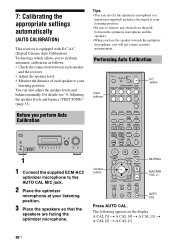
... [1] 30US You can also fix the optimizer microphone to your listening position. 3 Place the speakers so that the speakers are facing the optimizer microphone. Performing Auto Calibration Input buttons TV ?/1 AV ?/1 ?/1 RM SET UP P SYSTEM STANDBY SLEEP VIDEO1 VIDEO2 VIDEO3 DVD MD/TAPE SA-CD/CD TUNER AUX MULTI...CH IN MUTING 1 1 Connect the supplied ECM-AC2 optimizer microphone to the AUTO CAL MIC jack. 2 Place the optimizer microphone at your listening position. • Be sure to remove any obstacles in the path between each speaker and the receiver. • Adjust the speaker...
... [1] 30US You can also fix the optimizer microphone to your listening position. 3 Place the speakers so that the speakers are facing the optimizer microphone. Performing Auto Calibration Input buttons TV ?/1 AV ?/1 ?/1 RM SET UP P SYSTEM STANDBY SLEEP VIDEO1 VIDEO2 VIDEO3 DVD MD/TAPE SA-CD/CD TUNER AUX MULTI...CH IN MUTING 1 1 Connect the supplied ECM-AC2 optimizer microphone to the AUTO CAL MIC jack. 2 Place the optimizer microphone at your listening position. • Be sure to remove any obstacles in the path between each speaker and the receiver. • Adjust the speaker...


