Operation Guide
Page 3
... 2110 standard.2) HKCU-4002 12G-SDI Extension Kit Enables 12G-SDI output and 6G-SDI output. 1) To connect to the HDC-P43, an HKCU-SM100 CCU Extension Adaptor and a single-mode fiber cable are supported. 3 This unit may be combined with external equipment. HD normal speed video and SD normal speed...
... 2110 standard.2) HKCU-4002 12G-SDI Extension Kit Enables 12G-SDI output and 6G-SDI output. 1) To connect to the HDC-P43, an HKCU-SM100 CCU Extension Adaptor and a single-mode fiber cable are supported. 3 This unit may be combined with external equipment. HD normal speed video and SD normal speed...
Operation Guide
Page 5
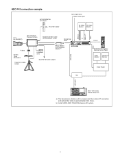
... Camera Single-mode fiber cable (ST connectors, 1 pair) Optical fiber cable V shoe VCT-14 Tripod Attachment Tripod for portable camera USB flash drive HKCU-SM100 CCU Extension Adapter a) Dual HD-SDI video outputs HDCU4300 LAN cable Hub BNC CCA-5 RCP-3000/1000 series Remote Control Panel Video Monitor Waveform Monitor Video...
... Camera Single-mode fiber cable (ST connectors, 1 pair) Optical fiber cable V shoe VCT-14 Tripod Attachment Tripod for portable camera USB flash drive HKCU-SM100 CCU Extension Adapter a) Dual HD-SDI video outputs HDCU4300 LAN cable Hub BNC CCA-5 RCP-3000/1000 series Remote Control Panel Video Monitor Waveform Monitor Video...

Operation Guide
Page 7
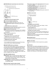
.... UNLOCK (Red): Not locked to either BRIDGE or MCS, this indicates that the unit cannot connect correctly with IP Live System Manager in the CCU menu. When CNS MODE on the page in the NETWORK menu is set in progress Flashing red: Not locked to LEGACY, this indicates that a...) Displays the GENLOCK status of the network. FAN STOP (Red): The fan is set to either BRIDGE or MCS, this remains turned off. d CCU number display Displays the camera number set to the REFERENCE input signal. Signal reception is unavailable. • NETWORK indicator (when HKCU-4001 is not connected...
.... UNLOCK (Red): Not locked to either BRIDGE or MCS, this indicates that the unit cannot connect correctly with IP Live System Manager in the CCU menu. When CNS MODE on the page in the NETWORK menu is set in progress Flashing red: Not locked to LEGACY, this indicates that a...) Displays the GENLOCK status of the network. FAN STOP (Red): The fan is set to either BRIDGE or MCS, this remains turned off. d CCU number display Displays the camera number set to the REFERENCE input signal. Signal reception is unavailable. • NETWORK indicator (when HKCU-4001 is not connected...
Operation Guide
Page 8
...CCU menu. PRIV: Blocks the connection to turn the power on the left (yellow) is lit: Reception status is low. This button lights in red when the power supply cord of other than an XLR 5-pin plug, consult a Sony... shorted. m Menu lock switch This locks out operation of the camera and CCU. When the lamp on , and switch to "a" to the producer line or engineer line, allowing private... intercom talk between the CCU and the camera. ENG: Connects the engineer line. • PRIV (private) indicator Lights ...
...CCU menu. PRIV: Blocks the connection to turn the power on the left (yellow) is lit: Reception status is low. This button lights in red when the power supply cord of other than an XLR 5-pin plug, consult a Sony... shorted. m Menu lock switch This locks out operation of the camera and CCU. When the lamp on , and switch to "a" to the producer line or engineer line, allowing private... intercom talk between the CCU and the camera. ENG: Connects the engineer line. • PRIV (private) indicator Lights ...
Operation Guide
Page 9
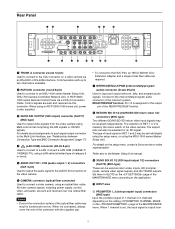
... from the video camera using an optical fiber cable. Communication with the supplied cap. • To connect to the HDC-P43, an HKCU-SM100 CCU Extension Adapter and a single-mode fiber cable are sent and received over one optical fiber cable. c 3G/HD SDI OUTPUT (SDI output) connector ...the end of the REAR PREVIEW function. The selection of RET 1 or 2 is assigned for an SD signal. Refer also to the CCU connector on the setup menu, contact a Sony service or sales representative. Control signals are sent and received via a CCA-5 Connection Cable. Rear Panel 12 3 45 6 7 8 ...
... from the video camera using an optical fiber cable. Communication with the supplied cap. • To connect to the HDC-P43, an HKCU-SM100 CCU Extension Adapter and a single-mode fiber cable are sent and received over one optical fiber cable. c 3G/HD SDI OUTPUT (SDI output) connector ...the end of the REAR PREVIEW function. The selection of RET 1 or 2 is assigned for an SD signal. Refer also to the CCU connector on the setup menu, contact a Sony service or sales representative. Control signals are sent and received via a CCA-5 Connection Cable. Rear Panel 12 3 45 6 7 8 ...
Operation Guide
Page 12
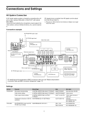
Connection example HD signals down-converted from 4K signals can be output from SLOT2 and SLOT3. 1) Requires an HKCU-SM100 CCU Extension Adaptor and singlemode fiber cable. The functions provided by the unit (genlock, power supply to SLOT3 Video output format of each slot Assignment of ...
Connection example HD signals down-converted from 4K signals can be output from SLOT2 and SLOT3. 1) Requires an HKCU-SM100 CCU Extension Adaptor and singlemode fiber cable. The functions provided by the unit (genlock, power supply to SLOT3 Video output format of each slot Assignment of ...

Operation Guide
Page 25
... status 6dB ND:1 CC:A 78 9 TALK 0 1/2000 OFF qa qs a CHU MODE indication Displays the CHU MODE (connected camera). For information on . Status Display The CCU system status can be monitored using the knob and levers in the MENU control block on , the camera settings page is displayed). To exit the...
... status 6dB ND:1 CC:A 78 9 TALK 0 1/2000 OFF qa qs a CHU MODE indication Displays the CHU MODE (connected camera). For information on . Status Display The CCU system status can be monitored using the knob and levers in the MENU control block on , the camera settings page is displayed). To exit the...

Operation Guide
Page 26
... status Power Supply: Camera power supply status Cable Length: Cable length Network Link Status: LAN connection status CCU No.: CCU number setting status Camera and unit audio status *Audio* Camera MIC Gain CH1 :60dB CH2 :60dB CCU Audio Out :AES/EBU 03/05 Camera MIC Gain CH1: Camera microphone circuit 1 amp gain status... Out: Output format of the AUDIO OUT connector of the unit Camera and unit intercom status *Intercom* Camera Engineer Producer CCU MIC/PGM Line :MIC On :MIC Off :MIC Off :System 04/05 Camera Engineer: Camera microphone status of the ENG line of the camera Camera ...
... status Power Supply: Camera power supply status Cable Length: Cable length Network Link Status: LAN connection status CCU No.: CCU number setting status Camera and unit audio status *Audio* Camera MIC Gain CH1 :60dB CH2 :60dB CCU Audio Out :AES/EBU 03/05 Camera MIC Gain CH1: Camera microphone circuit 1 amp gain status... Out: Output format of the AUDIO OUT connector of the unit Camera and unit intercom status *Intercom* Camera Engineer Producer CCU MIC/PGM Line :MIC On :MIC Off :MIC Off :System 04/05 Camera Engineer: Camera microphone status of the ENG line of the camera Camera ...

Operation Guide
Page 27
... HKCU-4001 is installed) *12G/6G-SDI Status* SDI OUT STATUS: SLOT1-2 OK 06/06 Displays any warning that occurs. Warning display *Alarm* CCU:DVP FAN STOP CCU:NETWORK ERROR 05/05 12G/6G-SDI connector output status (when HKCU-4002 is installed) *Network* LAN 1:Link up SPD 1:25G FEC 1:FC-FEC...
... HKCU-4001 is installed) *12G/6G-SDI Status* SDI OUT STATUS: SLOT1-2 OK 06/06 Displays any warning that occurs. Warning display *Alarm* CCU:DVP FAN STOP CCU:NETWORK ERROR 05/05 12G/6G-SDI connector output status (when HKCU-4002 is installed) *Network* LAN 1:Link up SPD 1:25G FEC 1:FC-FEC...

Operation Guide
Page 28
...Set the DISP/MENU lever to the ENTER position and pressing the CONTROL knob perform the same function. and intercom-related settings CCU configuration settings Network-related settings Displays the unit status. 28 Changing Menu Item Settings The menu screen is controlled using a video... monitor connected to TOP in the MENU control block on , the CCU MENU page is displayed. ** CCU MENU ** cSYSTEM OPERATION VIDEO/MONITOR AUDIO/INTERCOM MAINTENANCE NETWORK DIAGNOSIS Menu name SYSTEM OPERATION VIDEO/MONITOR AUDIO/INTERCOM MAINTENANCE NETWORK...
...Set the DISP/MENU lever to the ENTER position and pressing the CONTROL knob perform the same function. and intercom-related settings CCU configuration settings Network-related settings Displays the unit status. 28 Changing Menu Item Settings The menu screen is controlled using a video... monitor connected to TOP in the MENU control block on , the CCU MENU page is displayed. ** CCU MENU ** cSYSTEM OPERATION VIDEO/MONITOR AUDIO/INTERCOM MAINTENANCE NETWORK DIAGNOSIS Menu name SYSTEM OPERATION VIDEO/MONITOR AUDIO/INTERCOM MAINTENANCE NETWORK...

Operation Guide
Page 29
... display In menu display mode, set to the MENU position again to restart the operation. 3 Press the CONTROL knob. To select an item in the CCU MENU Turn the CONTROL knob to move the pointer (,) to the desired item, then press the CONTROL knob. The DISP/MENU lever can now be...
... display In menu display mode, set to the MENU position again to restart the operation. 3 Press the CONTROL knob. To select an item in the CCU MENU Turn the CONTROL knob to move the pointer (,) to the desired item, then press the CONTROL knob. The DISP/MENU lever can now be...

Operation Guide
Page 32
...) IP ADDRESS 2 b) (N04) NETWORK GENLOCK b) (N05) PTP STATUS b) (N06) IP LIVE a) b) (N05) a) (N07) b) IP ADDRESS SUBNET MASK DEFAULT GATEWAY MAC ADDRESS CNS MODE MCS MODE CCU NO MASTER IP ADDRESS TSL UMD PORT PORT NUMBER PACKET STATUS NETWORK INTERFACE DHCP IP ADDRESS SUBNET MASK DEFAULT GATEWAY MAC ADDRESS PORT DHCP IP...
...) IP ADDRESS 2 b) (N04) NETWORK GENLOCK b) (N05) PTP STATUS b) (N06) IP LIVE a) b) (N05) a) (N07) b) IP ADDRESS SUBNET MASK DEFAULT GATEWAY MAC ADDRESS CNS MODE MCS MODE CCU NO MASTER IP ADDRESS TSL UMD PORT PORT NUMBER PACKET STATUS NETWORK INTERFACE DHCP IP ADDRESS SUBNET MASK DEFAULT GATEWAY MAC ADDRESS PORT DHCP IP...

Operation Guide
Page 35
... the reference signal (fine adjustment) 0 to 7 Adjusts the vertical lock phase in the menu list table. ON, OFF Turns the optical signal output from the CCU to the camera ON/OFF. (Displayed only when connected using ENTER: Press the CONTROL knob or move the CANCEL/ENTER lever to the ENTER position...
... the reference signal (fine adjustment) 0 to 7 Adjusts the vertical lock phase in the menu list table. ON, OFF Turns the optical signal output from the CCU to the camera ON/OFF. (Displayed only when connected using ENTER: Press the CONTROL knob or move the CANCEL/ENTER lever to the ENTER position...

Operation Guide
Page 50
... area at the bottom right of the 4K color bar during 4K 2 sample interleave output. This function can easily identify the channel number of the CCU. -20, 0, +4 dBu Sets the AUDIO CH1 output level. -99 to 99 0 -20, 0, +4 dBu Sets the AUDIO CH2 output level. -99 to 99 0 50 MIC1/2: ... connector of a multi-link interface. 4K 2SI diamond marker This function is for displaying a test pattern like the following in the video area of the CCU. A01 Item CAM MIC GAIN CH1 CH2 A02 DELAY ANALOG OUT CH1 LEVEL ADJUST CH2 LEVEL ADJUST Set value Description Sets the camera microphone gain...
... area at the bottom right of the 4K color bar during 4K 2 sample interleave output. This function can easily identify the channel number of the CCU. -20, 0, +4 dBu Sets the AUDIO CH1 output level. -99 to 99 0 -20, 0, +4 dBu Sets the AUDIO CH2 output level. -99 to 99 0 50 MIC1/2: ... connector of a multi-link interface. 4K 2SI diamond marker This function is for displaying a test pattern like the following in the video area of the CCU. A01 Item CAM MIC GAIN CH1 CH2 A02 DELAY ANALOG OUT CH1 LEVEL ADJUST CH2 LEVEL ADJUST Set value Description Sets the camera microphone gain...

Operation Guide
Page 54
...YELLOW tally input setting Set to OFF to not display the CABLE OPEN alarm. STD: CONTROL knob clockwise rotation moves the CCU MENU pointer (,) down to ON, CCU menu operations cannot be added to not display the GENLOCK ERROR alarm. Sets the time zone. Selects the standard year of... there is output. MAINTENANCE Page name Page No. Turns the error-related page display function on the page. RVS: CONTROL knob counterclockwise rotation moves the CCU MENU pointer (,) down to 59 CONTACT, POWER(24V), POWER(TTL) CONTACT, POWER(24V), POWER(TTL) CONTACT, POWER(24V), POWER(TTL) OFF, ON...
...YELLOW tally input setting Set to OFF to not display the CABLE OPEN alarm. STD: CONTROL knob clockwise rotation moves the CCU MENU pointer (,) down to ON, CCU menu operations cannot be added to not display the GENLOCK ERROR alarm. Sets the time zone. Selects the standard year of... there is output. MAINTENANCE Page name Page No. Turns the error-related page display function on the page. RVS: CONTROL knob counterclockwise rotation moves the CCU MENU pointer (,) down to 59 CONTACT, POWER(24V), POWER(TTL) CONTACT, POWER(24V), POWER(TTL) CONTACT, POWER(24V), POWER(TTL) OFF, ON...

Operation Guide
Page 55
... to 255.255.255.255 MAC ADDRESS (xx:xx:xx:xx:xx:xx) CNS MODE LEGACY, BRIDGE, MCS MCS MODE CLIENT CCU NO MASTER IP ADDRESS TSL UMD PORT When MCS is selected in CNS MODE: Blank, 1 to 96 When LEGACY or BRIDGE is... ON Execute with ENTER. When received, it also displays IDs and the on the front panel. Reads the installation key from the CCU to the assignable button on /off status of the unit. NORMAL: Normal-speed signal HFR LINK: HFR signal 1LINK (steady image ... the MAC address of the red, green, and yellow tallies. "AND MORE" is selected. (Display only) Sets the CCU number.
... to 255.255.255.255 MAC ADDRESS (xx:xx:xx:xx:xx:xx) CNS MODE LEGACY, BRIDGE, MCS MCS MODE CLIENT CCU NO MASTER IP ADDRESS TSL UMD PORT When MCS is selected in CNS MODE: Blank, 1 to 96 When LEGACY or BRIDGE is... ON Execute with ENTER. When received, it also displays IDs and the on the front panel. Reads the installation key from the CCU to the assignable button on /off status of the unit. NORMAL: Normal-speed signal HFR LINK: HFR signal 1LINK (steady image ... the MAC address of the red, green, and yellow tallies. "AND MORE" is selected. (Display only) Sets the CCU number.
Operation Guide
Page 63
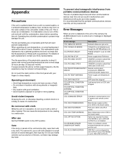
...operation, do not cover it to a warm location, or if ambient temperature suddenly rises, moisture may form on CCU side dropped CCU:OPTICAL CONDITION WARNING CCU:OPTICAL CONDITION CARE CCU:COMMAND ERROR Command communication error of these may damage the finish. To prevent electromagnetic interference from a cold to malfunction...and this unit. CCU:PLD CONFIG ERROR DPR PLD is not configured for HD CUTOUT when CHU MODE is set to cause it with cloth While the unit is in locations with strong electric or magnetic field. • Dry location with your Sony representative. The ...
...operation, do not cover it to a warm location, or if ambient temperature suddenly rises, moisture may form on CCU side dropped CCU:OPTICAL CONDITION WARNING CCU:OPTICAL CONDITION CARE CCU:COMMAND ERROR Command communication error of these may damage the finish. To prevent electromagnetic interference from a cold to malfunction...and this unit. CCU:PLD CONFIG ERROR DPR PLD is not configured for HD CUTOUT when CHU MODE is set to cause it with cloth While the unit is in locations with strong electric or magnetic field. • Dry location with your Sony representative. The ...