

Operater's Manual
Page 2
...cutting of established lawns and is important that you MUST have o these original instructions for purchasing this equipment. Mower Deck MFG Number Dealer Name Mower Deck SERIAL Number Date Purchased p NOTE: For location of Briggs & Stratton Power Products Group, LLC Milwaukee, WI, ...and understand these instructions thoroughly before attempting to avoid them. Save these numbers. These numbers can be found r in the SNAPPER brand. We're pleased that you aware of dependable service. Identification Numbers Product Identification Tag SA Model / Modèle ...
...cutting of established lawns and is important that you MUST have o these original instructions for purchasing this equipment. Mower Deck MFG Number Dealer Name Mower Deck SERIAL Number Date Purchased p NOTE: For location of Briggs & Stratton Power Products Group, LLC Milwaukee, WI, ...and understand these instructions thoroughly before attempting to avoid them. Save these numbers. These numbers can be found r in the SNAPPER brand. We're pleased that you aware of dependable service. Identification Numbers Product Identification Tag SA Model / Modèle ...

Operater's Manual
Page 3
... 24 Starting the Engine 16 PTO Clutch Adjustment 26 Stopping the Rider and Engine 16 Check Mower Blade Stoppping Time 26 Mowing 16 Mower Deck Leveling 27 Pushing the Rider by Hand 16 Servicing the Mower Blades 28 Zero Turn Driving Practice 17 Lubrication 29 Attaching a Trailer 19 ... Maintenance Chart 20 Checking Tire Pressures 21 r n Checking/Adding Fuel 21 Fuel Filter 21 fo tio Engine Maintenance 21 Washing the Mower Deck 22 RNeoptroduc Storage 22 Troubleshooting 31 Troubleshooting the Rider 31 Troubleshooting the Mower 32 Specifications 33 Warranties 34 3
... 24 Starting the Engine 16 PTO Clutch Adjustment 26 Stopping the Rider and Engine 16 Check Mower Blade Stoppping Time 26 Mowing 16 Mower Deck Leveling 27 Pushing the Rider by Hand 16 Servicing the Mower Blades 28 Zero Turn Driving Practice 17 Lubrication 29 Attaching a Trailer 19 ... Maintenance Chart 20 Checking Tire Pressures 21 r n Checking/Adding Fuel 21 Fuel Filter 21 fo tio Engine Maintenance 21 Washing the Mower Deck 22 RNeoptroduc Storage 22 Troubleshooting 31 Troubleshooting the Rider 31 Troubleshooting the Mower 32 Specifications 33 Warranties 34 3
Operater's Manual
Page 5
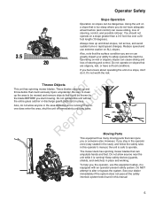
..., shut the unit off immediately until they leave. RNeprod Moving Parts This equipment has many moving parts that can amputate hands and feet. The mower deck has spinning mower blades that can injure you or someone else. To help you, the operator, use extreme caution on a slope greater than a 3.5 foot rise...
..., shut the unit off immediately until they leave. RNeprod Moving Parts This equipment has many moving parts that can amputate hands and feet. The mower deck has spinning mower blades that can injure you or someone else. To help you, the operator, use extreme caution on a slope greater than a 3.5 foot rise...
Operater's Manual
Page 8
...operate machine unless properly seated could cause injury if thrown by the manufacturer. machine if anyone enters the area. 6. underneath deck. while BLADES are clearly legible. Protect yourself when mowing and wear safety glass- 8. catcher or guards in daylight or ... is not pos- 1. R 7. birth defects, or other sources of control. Air Index information on the ground. If fuel is set. 8 www.Snapper.com ICES-002. Operator Safety Preparation 3. mowing. 5. Check shields, deflectors, switches, blade controls Set blades in motion. 10. Make sure all times....
...operate machine unless properly seated could cause injury if thrown by the manufacturer. machine if anyone enters the area. 6. underneath deck. while BLADES are clearly legible. Protect yourself when mowing and wear safety glass- 8. catcher or guards in daylight or ... is not pos- 1. R 7. birth defects, or other sources of control. Air Index information on the ground. If fuel is set. 8 www.Snapper.com ICES-002. Operator Safety Preparation 3. mowing. 5. Check shields, deflectors, switches, blade controls Set blades in motion. 10. Make sure all times....

Operater's Manual
Page 20
... AND MOWER ENGINE Every 8 Hours or Daily First 5 Hours Check safety interlock system Change engine oil Clean debris off rider and mower deck Every 8 Hours or Daily Clean debris from engine compartment Check engine oil level Every 25 Hours or Annually * Every 25 Hours or Annually...filter Clean engine air cooling system * Whichever comes first ** Clean more often in dusty conditions or when airborne debris is present. 20 www.Snapper.com See Dealer Annually to Replace air filter Lubricate rider and mower Replace pre-cleaner Clean battery and cables Check mower blades ** r n *...
... AND MOWER ENGINE Every 8 Hours or Daily First 5 Hours Check safety interlock system Change engine oil Clean debris off rider and mower deck Every 8 Hours or Daily Clean debris from engine compartment Check engine oil level Every 25 Hours or Annually * Every 25 Hours or Annually...filter Clean engine air cooling system * Whichever comes first ** Clean more often in dusty conditions or when airborne debris is present. 20 www.Snapper.com See Dealer Annually to Replace air filter Lubricate rider and mower Replace pre-cleaner Clean battery and cables Check mower blades ** r n *...
Operater's Manual
Page 22
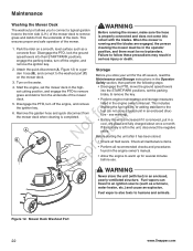
...allows you store your unit for several minutes before use. Before you to connect a typical garden hose to the trim side (L.H.) of the mower deck to remove grass and debris from the underside of the mower • Disengage the PTO, move the ground speed levers into the START/PARK ...battery is also toxic to an ignition source (such as a concrete floor. Fuel vapor is left in an enclosed, poorly ventilated structure. Mower Deck Washout Port 22 www.Snapper.com Attach the quick disconnect (A, Figure 12) to warm up for the off the engine, and remove r n the ignition key. Start the...
...allows you store your unit for several minutes before use. Before you to connect a typical garden hose to the trim side (L.H.) of the mower deck to remove grass and debris from the underside of the mower • Disengage the PTO, move the ground speed levers into the START/PARK ...battery is also toxic to an ignition source (such as a concrete floor. Fuel vapor is left in an enclosed, poorly ventilated structure. Mower Deck Washout Port 22 www.Snapper.com Attach the quick disconnect (A, Figure 12) to warm up for the off the engine, and remove r n the ignition key. Start the...
Operater's Manual
Page 24
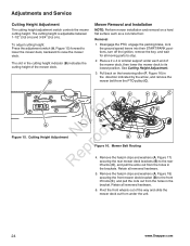
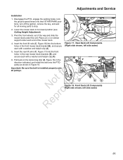
...duc D A roFigure 16. Pivot the front wheels out of the way and slide the mower deck out from the holes in the brackets. Place a 2 x 4 or similiar support under the unit. 24 www.Snapper.com Mower Belt Routing ep 4. The cutting height is adjustable between 1-1/2" (3,8 cm) and ...3-3/4" (9,5 cm). To adjust cutting height: Press the adjustment switch (A, Figure 15) forward to lower the mower deck, backward to the front lift rods (C), and...
...duc D A roFigure 16. Pivot the front wheels out of the way and slide the mower deck out from the holes in the brackets. Place a 2 x 4 or similiar support under the unit. 24 www.Snapper.com Mower Belt Routing ep 4. The cutting height is adjustable between 1-1/2" (3,8 cm) and ...3-3/4" (9,5 cm). To adjust cutting height: Press the adjustment switch (A, Figure 15) forward to lower the mower deck, backward to the front lift rods (C), and...
Operater's Manual
Page 25
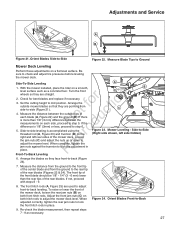
..., left side same) 25 t fo ctioC A B o u Figure 18. Adjustments and Service Installation 1. Place a 2 x 4 or similar support under the unit. Lower the mower deck to stop. 2. Figure 17. Disengage the PTO, engage the parking brake, lock the ground speed levers into the front holes in Figure 16. Front... idler (D, Figure 16) in the direction indicated, and install the belt onto the PTO pulley as shown in the rear mower deck brackets (B), and secure each with a washer and hairpin clip (A). Insert the rear lift arms (C, Figure 17) into their START/PARK posi-
..., left side same) 25 t fo ctioC A B o u Figure 18. Adjustments and Service Installation 1. Place a 2 x 4 or similar support under the unit. Lower the mower deck to stop. 2. Figure 17. Disengage the PTO, engage the parking brake, lock the ground speed levers into the front holes in Figure 16. Front... idler (D, Figure 16) in the direction indicated, and install the belt onto the PTO pulley as shown in the rear mower deck brackets (B), and secure each with a washer and hairpin clip (A). Insert the rear lift arms (C, Figure 17) into their START/PARK posi-

Operater's Manual
Page 26
.... This is turned off . 1. fo tio 1. NOTE: The actual air gap between the rotor and armature may vary even after every 250 hours of mower deck. Check the PTO clutch adjustment after the initial 25 hour break-in p Figure 20. Have an assistant observe the mower drive belt through each window... 19) until the rotor face and armature face just contacts the R gauge. o u 2. o 3. Also perform the following procedure if the clutch is turned off . 26 www.Snapper.com Adjustments and Service A B B B C Figure 20.
.... This is turned off . 1. fo tio 1. NOTE: The actual air gap between the rotor and armature may vary even after every 250 hours of mower deck. Check the PTO clutch adjustment after the initial 25 hour break-in p Figure 20. Have an assistant observe the mower drive belt through each window... 19) until the rotor face and armature face just contacts the R gauge. o u 2. o 3. Also perform the following procedure if the clutch is turned off . 26 www.Snapper.com Adjustments and Service A B B B C Figure 20.
Operater's Manual
Page 27
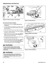
... with steps 8 - 9. 8. Adjust the front jam nuts (C) on a flat level surface. Adjustments and Service A B Figure 21. Be sure to adjust the mower deck level. Set the cutting height to step 5. If there o u is more than the rear tips of the rear blades (Figures 22 & 24). The front hitch... rods (A, Figure 25) are used to adjust front-to Ground Mower Deck Leveling Perform these adjustments on both front hitch rods. Measure Blade Tips to -back leveling. Side-to the rear tip of the rear blades. t ...
... with steps 8 - 9. 8. Adjust the front jam nuts (C) on a flat level surface. Adjustments and Service A B Figure 21. Be sure to adjust the mower deck level. Set the cutting height to step 5. If there o u is more than the rear tips of the rear blades (Figures 22 & 24). The front hitch... rods (A, Figure 25) are used to adjust front-to Ground Mower Deck Leveling Perform these adjustments on both front hitch rods. Measure Blade Tips to -back leveling. Side-to the rear tip of the rear blades. t ...
Operater's Manual
Page 28
Front-to prevent blade rotation while loosen- fo tio 3. Figure 27. Careless or improper handling of oil. Remove mower deck (see Mower Removal and Workbench Installation). 2. To remove blade for sharpening, use a block of wood r n (A, Figure 28) to ...washer, then securely tightened to a fine edge. Reinstall the blade washer (B, Figure 28), concave p side up toward the mower deck as shown in serious injury. 28 www.Snapper.com Mower Leveling - o 5. Re Torque hardware to prevent blade rotation while tightening the hardware. Blade Removal Servicing the Mower ...
Front-to prevent blade rotation while loosen- fo tio 3. Figure 27. Careless or improper handling of oil. Remove mower deck (see Mower Removal and Workbench Installation). 2. To remove blade for sharpening, use a block of wood r n (A, Figure 28) to ...washer, then securely tightened to a fine edge. Reinstall the blade washer (B, Figure 28), concave p side up toward the mower deck as shown in serious injury. 28 www.Snapper.com Mower Leveling - o 5. Re Torque hardware to prevent blade rotation while tightening the hardware. Blade Removal Servicing the Mower ...

Operater's Manual
Page 29
...caster wheel axles 2x • front caster spindle bosses • front axle center pivot • mower blade spindles * • mower deck idler arm • mower deck lift motor screw (located up under 2x right fender) Use grease fittings when present. Use automotive-type lithium grease. * Some blade ...spindles have grease fittings above the mower deck, while others listed in Figure 29, as well as the others have grease fittings below the deck. Keep oil and grease N d off belts and pulleys. Disassemble parts to apply grease...
...caster wheel axles 2x • front caster spindle bosses • front axle center pivot • mower blade spindles * • mower deck idler arm • mower deck lift motor screw (located up under 2x right fender) Use grease fittings when present. Use automotive-type lithium grease. * Some blade ...spindles have grease fittings above the mower deck, while others listed in Figure 29, as well as the others have grease fittings below the deck. Keep oil and grease N d off belts and pulleys. Disassemble parts to apply grease...

Operater's Manual
Page 32
... authorized service dealer. Steering linkage is uneven. Improper tire inflation. Mower cut is oily or worn. LOOK FOR REMEDY Mower deck not properly installed. Engine speed too slow. Decrease ground speed. c Blades are bent. Sharpen or replace blades. Blades not..., and balance blades. Excessive belt wear or breakage. See authorized service dealer. See authorized service dealer. 32 www.Snapper.com Troubleshooting PROBLEM Rider drive belt slips. Brake will not raise. Internal transmission problem. Engine stalls easily with discharge pointing toward...
... authorized service dealer. Steering linkage is uneven. Improper tire inflation. Mower cut is oily or worn. LOOK FOR REMEDY Mower deck not properly installed. Engine speed too slow. Decrease ground speed. c Blades are bent. Sharpen or replace blades. Blades not..., and balance blades. Excessive belt wear or breakage. See authorized service dealer. See authorized service dealer. 32 www.Snapper.com Troubleshooting PROBLEM Rider drive belt slips. Brake will not raise. Internal transmission problem. Engine stalls easily with discharge pointing toward...
