
Service Manual
Page 1
...S6710R930APW/ SMART & EASYCONVECTION MIX CONV DEFROST SENSOR COOK LBS OZ KG HELP Interactive CUSTOM HELP SENSOR REHEAT MINUTE PLUS POPCORN ELEVATE PKG COMPU DEFROST 1 2 3 4 5 6 7 FBFFFHrrrraoeoeoktszszedehhedonnvvgpveeesoeggntg--tashreteoaotaefretbdssles Bacon 8 Fish, seafood SENSOR COOKT Convection 1 2 3 SHCtahem iackkbesunrgpeiersces 4 Fish ...AND ADJUSTMENT PROCEDURE 27 PICTORIAL DIAGRAM ...33 CONTROL PANEL CIRCUIT ...34 PRINTED WIRING BOARD ...35 PARTS LIST ...36 PACKING AND ACCESSORIES ...39 SHARP ELECTRONICS CORPORATION Service Headquarters: Sharp Plaza, Mahwah, New ...
...S6710R930APW/ SMART & EASYCONVECTION MIX CONV DEFROST SENSOR COOK LBS OZ KG HELP Interactive CUSTOM HELP SENSOR REHEAT MINUTE PLUS POPCORN ELEVATE PKG COMPU DEFROST 1 2 3 4 5 6 7 FBFFFHrrrraoeoeoktszszedehhedonnvvgpveeesoeggntg--tashreteoaotaefretbdssles Bacon 8 Fish, seafood SENSOR COOKT Convection 1 2 3 SHCtahem iackkbesunrgpeiersces 4 Fish ...AND ADJUSTMENT PROCEDURE 27 PICTORIAL DIAGRAM ...33 CONTROL PANEL CIRCUIT ...34 PRINTED WIRING BOARD ...35 PARTS LIST ...36 PACKING AND ACCESSORIES ...39 SHARP ELECTRONICS CORPORATION Service Headquarters: Sharp Plaza, Mahwah, New ...

Service Manual
Page 5
... the SHARP CONVECTION MICROWAVE OVENS R930AK / R-930AW. Special attention should be qualified to avoid electrical shock and microwave radiation hazard. Check the interlock switches and the door seal carefully. R-930AK R-930AW PRODUCT DESCRIPTION GENERAL INFORMATION OPERATION TROUBLESHOOTING GUIDE AND TEST PROCEDURE TOUCH CONTROL PANEL COMPONENT REPLACEMENT AND ADJUSTMENT PROCEDURE WIRING DIAGRAM PARTS LIST SHARP ELECTRONICS CORPORATION SHARP...
... the SHARP CONVECTION MICROWAVE OVENS R930AK / R-930AW. Special attention should be qualified to avoid electrical shock and microwave radiation hazard. Check the interlock switches and the door seal carefully. R-930AK R-930AW PRODUCT DESCRIPTION GENERAL INFORMATION OPERATION TROUBLESHOOTING GUIDE AND TEST PROCEDURE TOUCH CONTROL PANEL COMPONENT REPLACEMENT AND ADJUSTMENT PROCEDURE WIRING DIAGRAM PARTS LIST SHARP ELECTRONICS CORPORATION SHARP...

Service Manual
Page 29
... voltage capacitor and High voltage rectifier assembly. 2) Hot parts: Oven lamp, Magnetron, High voltage transformer and Oven cavity. 3) Sharp edge: Bottom plate, Oven cavity, Weveguide flange, Chassis support and other metallic plate. 4) Movable parts (to the Pictorial diagram. 4. Slide the entire case back out about 1 inch...rear plate with the one (1) hole of the switch holder to the one (1) retaining tab holding the switch holder to the Pictorial Diagram. Before wiring, 1) Disconnect the power supply. 2) Open the door and wedge the door open. 3) Discharge the high voltage capacitor ...
... voltage capacitor and High voltage rectifier assembly. 2) Hot parts: Oven lamp, Magnetron, High voltage transformer and Oven cavity. 3) Sharp edge: Bottom plate, Oven cavity, Weveguide flange, Chassis support and other metallic plate. 4) Movable parts (to the Pictorial diagram. 4. Slide the entire case back out about 1 inch...rear plate with the one (1) hole of the switch holder to the one (1) retaining tab holding the switch holder to the Pictorial Diagram. Before wiring, 1) Disconnect the power supply. 2) Open the door and wedge the door open. 3) Discharge the high voltage capacitor ...
Service Manual
Page 33
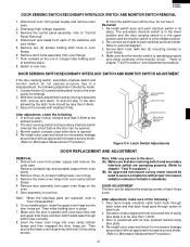
... hook assembly from power supply and remove outer case. 2. Re-install switch lever and each switches and fuse holder. Refer to pictorial diagram. 3. Re-install outer case and check for microwave leakage around door with two (2) mounting screws) to Microwave Measurement Procedure.) 31 Remove... lose it back and forth, and up and down. Latch Switch Adjustments DOOR REPLACEMENT AND ADJUSTMENT REMOVAL 1. Note: When the individual parts are operating properly. (Refer to a misadjustment, the following adjustment should be adjusted by moving it . Secure the screws with tree ...
... hook assembly from power supply and remove outer case. 2. Re-install switch lever and each switches and fuse holder. Refer to pictorial diagram. 3. Re-install outer case and check for microwave leakage around door with two (2) mounting screws) to Microwave Measurement Procedure.) 31 Remove... lose it back and forth, and up and down. Latch Switch Adjustments DOOR REPLACEMENT AND ADJUSTMENT REMOVAL 1. Note: When the individual parts are operating properly. (Refer to a misadjustment, the following adjustment should be adjusted by moving it . Secure the screws with tree ...

Service Manual
Page 38
... lamp Oven lamp (Interchangeable) Oven lamp socket Convection fan motor Fan motor Heating element Power transformer H.V.capacitor H.V.capacitor (Interchangeable) H.V.rectifier assembly Magnetron Magnetron (Interchangeable) Magnetron (Interchangeable) Turntable motor AH sensor assembly Q'TY 1 1 1 3 1 2 1 1 1 1 1 1 1 1 1 1 1 1 1 1 1 1 1 1 CABINET PARTS 2- 1 GCABUA463WRP0 Outer case cabinet [R-930AW] 1 2- 1 GCABUA457WRP0 Outer case cabinet [R-930AK] 1 2- 2 TMAPCA732WRR0 Schematic diagram 1 2- 3 FDAI-A179WRY0 Base cabinet 1 2- 3-1 GCOVHA156WRP0 Turntable motor...
... lamp Oven lamp (Interchangeable) Oven lamp socket Convection fan motor Fan motor Heating element Power transformer H.V.capacitor H.V.capacitor (Interchangeable) H.V.rectifier assembly Magnetron Magnetron (Interchangeable) Magnetron (Interchangeable) Turntable motor AH sensor assembly Q'TY 1 1 1 3 1 2 1 1 1 1 1 1 1 1 1 1 1 1 1 1 1 1 1 1 CABINET PARTS 2- 1 GCABUA463WRP0 Outer case cabinet [R-930AW] 1 2- 1 GCABUA457WRP0 Outer case cabinet [R-930AK] 1 2- 2 TMAPCA732WRR0 Schematic diagram 1 2- 3 FDAI-A179WRY0 Base cabinet 1 2- 3-1 GCOVHA156WRP0 Turntable motor...


