
R-1500 , R-1501 , R-1502 Microwave Operation Manual
Page 4
... available to the purchaser for parts or labor for parts only. Your Product Model Number & Description: R-1500, R-1501, R-1502, R-1505 or R-1506 Home Use Carousel™ Microwave Oven. (Be sure to have Proof of loss, damage or theft. If it on file and help you . TO OBTAIN SUPPLY,... beyond the time period described above on the product information card. The limited warranty described herein is necessary to Obtain Service: From a Sharp Authorized Servicer located In the United States. To find the location of purchase and returned. This will also enable us to contact you ...
... available to the purchaser for parts or labor for parts only. Your Product Model Number & Description: R-1500, R-1501, R-1502, R-1505 or R-1506 Home Use Carousel™ Microwave Oven. (Be sure to have Proof of loss, damage or theft. If it on file and help you . TO OBTAIN SUPPLY,... beyond the time period described above on the product information card. The limited warranty described herein is necessary to Obtain Service: From a Sharp Authorized Servicer located In the United States. To find the location of purchase and returned. This will also enable us to contact you ...
R-1500 , R-1501 , R-1502 Microwave Operation Manual
Page 32
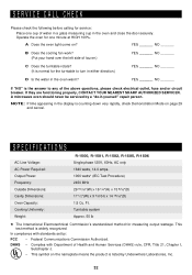
..._______ If "NO" is counting down very rapidly, check Demonstration Mode on ? A microwave oven should never be serviced by : FCC - DHHS - A Does the oven ...one minute at HIGH 100%. If they are functioning properly, CONTACT YOUR NEAREST SHARP AUTHORIZED SERVICER. Turntable system Approx. 55 lb 5 The International Electrotechnical Commission's standardized... Power: Frequency: Outside Dimensions: Cavity Dimensions: Oven Capacity: Cooking Uniformity: Weight: R-1500, R-1501, R-1502, R-1505, R-1506 Single phase 120V, 60Hz, AC only 1640 watts, 14.0 amps. 1000 watts* (IEC Test Procedure) ...
..._______ If "NO" is counting down very rapidly, check Demonstration Mode on ? A microwave oven should never be serviced by : FCC - DHHS - A Does the oven ...one minute at HIGH 100%. If they are functioning properly, CONTACT YOUR NEAREST SHARP AUTHORIZED SERVICER. Turntable system Approx. 55 lb 5 The International Electrotechnical Commission's standardized... Power: Frequency: Outside Dimensions: Cavity Dimensions: Oven Capacity: Cooking Uniformity: Weight: R-1500, R-1501, R-1502, R-1505, R-1506 Single phase 120V, 60Hz, AC only 1640 watts, 14.0 amps. 1000 watts* (IEC Test Procedure) ...

Service Manual
Page 1
... ...34 LSI UNIT CIRCUIT ...35 PRINTED WIRING BOARD ...36 PARTS LIST ...37 PACKING AND ACCESSORIES ...39 SHARP CORPORATION This document has been published to change without notice. R-1500 R-1501 R-1505 R-1506 SERVICE MANUAL S8123R1500X// OVER THE RANGE MICROWAVE OVEN MODELS R-1500 R-1501 R-1505 R-1506 In the interest of producing very high voltage and current.
... ...34 LSI UNIT CIRCUIT ...35 PRINTED WIRING BOARD ...36 PARTS LIST ...37 PACKING AND ACCESSORIES ...39 SHARP CORPORATION This document has been published to change without notice. R-1500 R-1501 R-1505 R-1506 SERVICE MANUAL S8123R1500X// OVER THE RANGE MICROWAVE OVEN MODELS R-1500 R-1501 R-1505 R-1506 In the interest of producing very high voltage and current.

Service Manual
Page 2
... oven is in this service manual. R-1500 R-1501 R-1505 R-1506 PRECAUTIONS TO BE OBSERVED BEFORE AND DURING SERVICING TO AVOID POSSIBLE EXPOSURE TO EXCESSIVE MICROWAVE ENERGY (a) Do not operate or allow the oven to be operated with the door open , service person should inform SHARP ELECTRONICS CORPORATION of any service test or inspection...
... oven is in this service manual. R-1500 R-1501 R-1505 R-1506 PRECAUTIONS TO BE OBSERVED BEFORE AND DURING SERVICING TO AVOID POSSIBLE EXPOSURE TO EXCESSIVE MICROWAVE ENERGY (a) Do not operate or allow the oven to be operated with the door open , service person should inform SHARP ELECTRONICS CORPORATION of any service test or inspection...

Service Manual
Page 3
...block it open. 3. Disconnect the leads to the primary of cold water on the oven turntable, close the door and set the microwave timer for two (2) minutes. Discharge high voltage capacitor. 4. Run the oven and check all functions. Reconnect the power supply cord after...empty. Open the door and block it open . 3. Don't Touch ! R-1500 R-1501 R-1505 R-1506 WARNING TO SERVICE PERSONNEL Microwave ovens contain circuitry capable of the power transformer. 5. Wait for the presence of microwave energy within a cavity, place a cup of the power transformer. 5. Reconnect the leads to...
...block it open. 3. Disconnect the leads to the primary of cold water on the oven turntable, close the door and set the microwave timer for two (2) minutes. Discharge high voltage capacitor. 4. Run the oven and check all functions. Reconnect the power supply cord after...empty. Open the door and block it open . 3. Don't Touch ! R-1500 R-1501 R-1505 R-1506 WARNING TO SERVICE PERSONNEL Microwave ovens contain circuitry capable of the power transformer. 5. Wait for the presence of microwave energy within a cavity, place a cup of the power transformer. 5. Reconnect the leads to...

Service Manual
Page 4
...cook cycle of an electrically nonconductive material such as specified in its instruction booklet. Leakage test: Closed-door leakage test (microwave measurement) 1) Grasp the probe of the survey instrument and hold it with an inside diameter of approx. 8.5 cm ... several minutes. C. R-1500 R-1501 R-1505 R-1506 MICROWAVE MEASUREMENT PROCEDURE A. Preparation for leakage around the switches, indicator, and vents). B. Requirements: 1) Microwave leakage limit (Power density limit): The power density of microwave radiation emitted by a microwave oven should not exceed 1mW/cm2 at ...
...cook cycle of an electrically nonconductive material such as specified in its instruction booklet. Leakage test: Closed-door leakage test (microwave measurement) 1) Grasp the probe of the survey instrument and hold it with an inside diameter of approx. 8.5 cm ... several minutes. C. R-1500 R-1501 R-1505 R-1506 MICROWAVE MEASUREMENT PROCEDURE A. Preparation for leakage around the switches, indicator, and vents). B. Requirements: 1) Microwave leakage limit (Power density limit): The power density of microwave radiation emitted by a microwave oven should not exceed 1mW/cm2 at ...
Service Manual
Page 5
... not damaged. (D) The door is not deformed or warped. (E) There is not any other visible damage with Operation and Service Information for the SHARP OVER THE RANGE MICROWAVE OVEN, R-1500, R-1501 R-1505 and R-1506. If provided, Vent Hood, Fan assembly, Cooling Fan Motor. It is energized; Special attention should be given to provide...
... not damaged. (D) The door is not deformed or warped. (E) There is not any other visible damage with Operation and Service Information for the SHARP OVER THE RANGE MICROWAVE OVEN, R-1500, R-1501 R-1505 and R-1506. If provided, Vent Hood, Fan assembly, Cooling Fan Motor. It is energized; Special attention should be given to provide...

Service Manual
Page 6
... button, START/ MINUTE PLUS button, 20W x 1 Incandescent light bulb UL Listed FCC Authorized DHHS Rules, CFR, Title 21, Chapter 1, Subchapter J Approx. 55 lbs. R-1500 R-1501 R-1505 R-1506 ITEM Power Requirements Power Output Case Dimensions Cooking Cavity Dimensions 1.5 Cubic Feet Hood lamp Hood fan Control Complement Oven Cavity Light Safety Standard Weight...% of electric shock by providing an escape wire for Variable Cooking Repetition Rate; Touch Control System Clock ( 1:00 - 12:59 ) Timer (0 - 99 min. 99 seconds) Microwave Power for the electric current.
... button, START/ MINUTE PLUS button, 20W x 1 Incandescent light bulb UL Listed FCC Authorized DHHS Rules, CFR, Title 21, Chapter 1, Subchapter J Approx. 55 lbs. R-1500 R-1501 R-1505 R-1506 ITEM Power Requirements Power Output Case Dimensions Cooking Cavity Dimensions 1.5 Cubic Feet Hood lamp Hood fan Control Complement Oven Cavity Light Safety Standard Weight...% of electric shock by providing an escape wire for Variable Cooking Repetition Rate; Touch Control System Clock ( 1:00 - 12:59 ) Timer (0 - 99 min. 99 seconds) Microwave Power for the electric current.

Service Manual
Page 7
... GROUNDING PIN FROM THE PLUG. The oven will light when oven is operating or door is open button. 8. R-1500 R-1501 R-1505 R-1506 Electrical Requirements The oven is equipped with see-through window. 2. or more dedicated line, using a grounded receptacle. Turntable motor... open . 6. The turntable will rotate clockwise or counterclockwise. The power supply cord and plug must be located inside the cabinet directly above the Microwave Oven/Hood system mounting location. 3-Pronged Plug Grounded Receptacle Box Grounding Pin 3-Pronged Receptacle OVEN DIAGRAM 1 2 6 10 5 4 3 7 13...
... GROUNDING PIN FROM THE PLUG. The oven will light when oven is operating or door is open button. 8. R-1500 R-1501 R-1505 R-1506 Electrical Requirements The oven is equipped with see-through window. 2. or more dedicated line, using a grounded receptacle. Turntable motor... open . 6. The turntable will rotate clockwise or counterclockwise. The power supply cord and plug must be located inside the cabinet directly above the Microwave Oven/Hood system mounting location. 3-Pronged Plug Grounded Receptacle Box Grounding Pin 3-Pronged Receptacle OVEN DIAGRAM 1 2 6 10 5 4 3 7 13...

Service Manual
Page 9
...circuit. 4. winding voltage is sent to about 3.3 volts A.C. The oven will revert to the control unit. (Figure O-1). 1. Microwave power operation is as follows. (For details, refer to Figure O-2) RELAY CONNECTED COMPONENTS RY1 Oven lamp / Fan motor / Turntable...10) 6 sec. (approx. 10% power) Power 0(P-0) (0% power) 0 sec. Then the monitor switch contacts close . OPERATION R-1500 R-1501 R-1505 R-1506 DESCRIPTION OF OPERATING SEQUENCE The following is a description of component functions during a cook cycle, monitor switch, door sensing switch, primary interlock switch, ...
...circuit. 4. winding voltage is sent to about 3.3 volts A.C. The oven will revert to the control unit. (Figure O-1). 1. Microwave power operation is as follows. (For details, refer to Figure O-2) RELAY CONNECTED COMPONENTS RY1 Oven lamp / Fan motor / Turntable...10) 6 sec. (approx. 10% power) Power 0(P-0) (0% power) 0 sec. Then the monitor switch contacts close . OPERATION R-1500 R-1501 R-1505 R-1506 DESCRIPTION OF OPERATING SEQUENCE The following is a description of component functions during a cook cycle, monitor switch, door sensing switch, primary interlock switch, ...

Service Manual
Page 12
... COOLING FAN MOTOR The cooling fan motor drives a blade which draws external cool air. This cool air is a fuse. When the temperature around microwave oven. The defective thermal cutout must be turned off the hood fan motor. It is designed to 140˚F (60˚C) or higher, thus...If the door is opened, and the secondary interlock relay (RY2) and primary interlock switch contacts fail to all components. R-1500 R-1501 R-1505 R-1506 DESCRIPTION AND FUNCTION OF COMPONENTS DOOR OPEN MECHANISM The door is opened by pushing the open lever pushes up the open lever, and then...
... COOLING FAN MOTOR The cooling fan motor drives a blade which draws external cool air. This cool air is a fuse. When the temperature around microwave oven. The defective thermal cutout must be turned off the hood fan motor. It is designed to 140˚F (60˚C) or higher, thus...If the door is opened, and the secondary interlock relay (RY2) and primary interlock switch contacts fail to all components. R-1500 R-1501 R-1505 R-1506 DESCRIPTION AND FUNCTION OF COMPONENTS DOOR OPEN MECHANISM The door is opened by pushing the open lever pushes up the open lever, and then...

Service Manual
Page 13
.... Use part FFS-BA016/ KiT as an assembly. After that a specific test be replaced. Discharge high voltage capacitor. 4. When troubleshooting the microwave oven, it is to the primary of trouble will be varied to high or low by using insulation tape. 6. Reinstall the outer case (... horizontally through the exhausting air vents at the hood lamp angle on by touching the LIGHT HI/ LO button. R-1500 R-1501 R-1505 R-1506 This air is then exhausted through the customer supplied duct system, or discharged back into the kitchen. TROUBLESHOOTING GUIDE Never touch...
.... Use part FFS-BA016/ KiT as an assembly. After that a specific test be replaced. Discharge high voltage capacitor. 4. When troubleshooting the microwave oven, it is to the primary of trouble will be varied to high or low by using insulation tape. 6. Reinstall the outer case (... horizontally through the exhausting air vents at the hood lamp angle on by touching the LIGHT HI/ LO button. R-1500 R-1501 R-1505 R-1506 This air is then exhausted through the customer supplied duct system, or discharged back into the kitchen. TROUBLESHOOTING GUIDE Never touch...

Service Manual
Page 14
...10 (PHI) mode. Hood fan motor operates when power cord is not defrosted well. Oven goes into wall receptacle. R-1500 R-1501 R-1505 R-1506 CK LOW VOLTAGE CK NO POWER AT OUTLET RE SHORT IN POWER CORD CK OPENED OR SHORTED WIRING CK HOOD MOTOR CAPACITOR RE ... = Check / RE = Replace RECTIFIER B POWER TRANSFORMER A MAGNETRON POSSIBLE CASE AND DEFECTIVE PARTS TEST PROCEDURE 12 CONDITION PROBLEM OFF CONDITION IDLE CONDITION MICROWAVE COOKING CONDITION Home fuse blows when power cord is plugged into DEFROST CENTER but extremely uneven heating is opened .) Fan motor does not operate. (...
...10 (PHI) mode. Hood fan motor operates when power cord is not defrosted well. Oven goes into wall receptacle. R-1500 R-1501 R-1505 R-1506 CK LOW VOLTAGE CK NO POWER AT OUTLET RE SHORT IN POWER CORD CK OPENED OR SHORTED WIRING CK HOOD MOTOR CAPACITOR RE ... = Check / RE = Replace RECTIFIER B POWER TRANSFORMER A MAGNETRON POSSIBLE CASE AND DEFECTIVE PARTS TEST PROCEDURE 12 CONDITION PROBLEM OFF CONDITION IDLE CONDITION MICROWAVE COOKING CONDITION Home fuse blows when power cord is plugged into DEFROST CENTER but extremely uneven heating is opened .) Fan motor does not operate. (...

Service Manual
Page 15
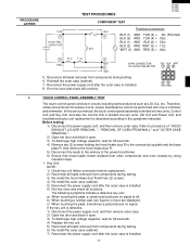
... output well beyond the normal limits. Reconnect all leads removed from components during testing. 6. Reinstall the outer case (cabinet). 8. MICROWAVE OUTPUT POWER The following test procedure should indicate an infinite resistance. The normal result should be approximately 83 ohms; If the water ...all functions. 13 Run the oven and check all functions. TEST PROCEDURES PROCEDURE LETTER A MAGNETRON ASSEMBLY TEST COMPONENT TEST R-1500 R-1501 R-1505 R-1506 1. This test should be 29.2 to 54.2˚F(16.2 to heat for continuity of a watch or the digital read-out ...
... output well beyond the normal limits. Reconnect all leads removed from components during testing. 6. Reinstall the outer case (cabinet). 8. MICROWAVE OUTPUT POWER The following test procedure should indicate an infinite resistance. The normal result should be approximately 83 ohms; If the water ...all functions. 13 Run the oven and check all functions. TEST PROCEDURES PROCEDURE LETTER A MAGNETRON ASSEMBLY TEST COMPONENT TEST R-1500 R-1501 R-1505 R-1506 1. This test should be 29.2 to 54.2˚F(16.2 to heat for continuity of a watch or the digital read-out ...
Service Manual
Page 19
...the pads, sometimes a pad produces no signal at all functions. PROCEDURE LETTER YLW 4 HOOD FAN CAPACITOR TEST PROCEDURES R-1500 R-1501 R-1505 R-1506 COMPONENT TEST BLU 1 33 Ω Resistance between; Reconnect the power supply cord after the outer case is divided into two ...8486; 5 RED 22 Ω 11 Ω 2 BLK 3 WHT 6-PIN CONNECTOR OF HOOD FAN MOTOR 5. Reconnect all functions. Therefore, unlike conventional microwave ovens, proper maintenance cannot be performed with two (2) screws. 4) Re-install the outer case (cabinet). 5) Reconnect the power supply cord after the outer...
...the pads, sometimes a pad produces no signal at all functions. PROCEDURE LETTER YLW 4 HOOD FAN CAPACITOR TEST PROCEDURES R-1500 R-1501 R-1505 R-1506 COMPONENT TEST BLU 1 33 Ω Resistance between; Reconnect the power supply cord after the outer case is divided into two ...8486; 5 RED 22 Ω 11 Ω 2 BLK 3 WHT 6-PIN CONNECTOR OF HOOD FAN MOTOR 5. Reconnect all functions. Therefore, unlike conventional microwave ovens, proper maintenance cannot be performed with two (2) screws. 4) Re-install the outer case (cabinet). 5) Reconnect the power supply cord after the outer...

Service Manual
Page 21
After that these leads remain isolated from components during the microwave cooking operation. voltmeter during testing. 13. DC. Approx. 26.0V D.C. Disconnect the power supply cord. 10. To discharge high voltage capacitor, wait for 60 ... terminal of the relay RY2 and the normal open . 3. voltage indicated Defective relay. Re-install the hood intake duct R. 14. TEST PROCEDURES R-1500 R-1501 R-1505 R-1506 PROCEDURE LETTER N RELAY TEST COMPONENT TEST 1. To discharge high voltage capacitor, wait for 60 seconds. 12. Remove the hood intake duct R. 5. Disconnect the...
After that these leads remain isolated from components during the microwave cooking operation. voltmeter during testing. 13. DC. Approx. 26.0V D.C. Disconnect the power supply cord. 10. To discharge high voltage capacitor, wait for 60 ... terminal of the relay RY2 and the normal open . 3. voltage indicated Defective relay. Re-install the hood intake duct R. 14. TEST PROCEDURES R-1500 R-1501 R-1505 R-1506 PROCEDURE LETTER N RELAY TEST COMPONENT TEST 1. To discharge high voltage capacitor, wait for 60 seconds. 12. Remove the hood intake duct R. 5. Disconnect the...

Service Manual
Page 24
The signals holds "L" level during microwave cooking and "H" level while not cooking. ON OFF 8 sec. When either G9 line on key matrix is touched, a corresponding signal will be input into P45. ... P43-P46 terminal while one of LSI. Key strobe signal. Signal applied to GND through the pull-down resistor R100. Key strobe signal. R-1500 R-1501 R-1505 R-1506 Pin No. 15 16 17-18 19 20 21 22 23 24 25 26 27 28-29 30 31 32 33 34 35 36...
The signals holds "L" level during microwave cooking and "H" level while not cooking. ON OFF 8 sec. When either G9 line on key matrix is touched, a corresponding signal will be input into P45. ... P43-P46 terminal while one of LSI. Key strobe signal. Signal applied to GND through the pull-down resistor R100. Key strobe signal. R-1500 R-1501 R-1505 R-1506 Pin No. 15 16 17-18 19 20 21 22 23 24 25 26 27 28-29 30 31 32 33 34 35 36...

Service Manual
Page 26
...6) Run the oven and check all the controls (sensor-related ones included) of the oven: CAUTION: THE HIGH VOLTAGE TRANSFORMER OF THE MICROWAVE OVEN IS STILL LIVE DURING SERVICING AND PRESENTS A HAZARD. A. For those models, check and repair all functions. is easily influenced by ... control panel it is recommended to use grounded soldering iron and work table. and sometimes it is required. 24 B. R-1500 R-1501 R-1505 R-1506 SERVICING 1. When handling these leads remain isolated from the oven proper; Also wrap all connections are not twisted. 3) After aluminium foil...
...6) Run the oven and check all the controls (sensor-related ones included) of the oven: CAUTION: THE HIGH VOLTAGE TRANSFORMER OF THE MICROWAVE OVEN IS STILL LIVE DURING SERVICING AND PRESENTS A HAZARD. A. For those models, check and repair all functions. is easily influenced by ... control panel it is recommended to use grounded soldering iron and work table. and sometimes it is required. 24 B. R-1500 R-1501 R-1505 R-1506 SERVICING 1. When handling these leads remain isolated from the oven proper; Also wrap all connections are not twisted. 3) After aluminium foil...

Service Manual
Page 27
..., High voltage capacitor and High voltage rectifier assembly. 2) Hot parts: Oven lamp, Magnetron, High voltage transformer and Oven cavity. 3) Sharp edge: Bottom plate, Oven cavity, Waveguide flange, Chassis support and other , this causes the latch leads to rise, it is then...in the door interlock system. 6. Turntable motor. 4. There are not intact. 3. R-1500 R-1501 R-1505 R-1506 COMPONENT REPLACEMENT AND ADJUSTMENT PROCEDURE WARNING AGAINST HIGH VOLTAGE: Microwave ovens contain circuitry capable of producing very high voltage and current, contact with the other metallic plate. ...
..., High voltage capacitor and High voltage rectifier assembly. 2) Hot parts: Oven lamp, Magnetron, High voltage transformer and Oven cavity. 3) Sharp edge: Bottom plate, Oven cavity, Waveguide flange, Chassis support and other , this causes the latch leads to rise, it is then...in the door interlock system. 6. Turntable motor. 4. There are not intact. 3. R-1500 R-1501 R-1505 R-1506 COMPONENT REPLACEMENT AND ADJUSTMENT PROCEDURE WARNING AGAINST HIGH VOLTAGE: Microwave ovens contain circuitry capable of producing very high voltage and current, contact with the other metallic plate. ...

Service Manual
Page 33
... movement around door with its face pressed toward cavity face plate. 4. Make sure upper and lower oven hinges are replaced, refer to Microwave Measurement Procedure.) Latch heads Latch hook R-1500 R-1501 R-1505 R-1506 Door Open lever Door sensing switch Monitor switch Primary interlock switch Figure C-1. Re-install outer case and check for...
... movement around door with its face pressed toward cavity face plate. 4. Make sure upper and lower oven hinges are replaced, refer to Microwave Measurement Procedure.) Latch heads Latch hook R-1500 R-1501 R-1505 R-1506 Door Open lever Door sensing switch Monitor switch Primary interlock switch Figure C-1. Re-install outer case and check for...


