Service Manual
Page 1
SHARP CORPORATION This document has been published to change without prior notice. The contents are subject to be used . 1st Edition 32F630 32F631 SERVICE MANUAL S13W527F630// COLOR TELEVISION Chassis No. CONTENTS Page » ELECTRICAL SPECIFICATIONS ...1 » IMPORTANT SERVICE SAFETY... Plan U.S.A.) Specifications are subject to those specified should be restored to its original condition and only parts identical to change without notice. GB-3U 32F630 32F630 32F631 MODELS 32F631 In the interests of user-safety (Required by safety regulations in some countries )...
SHARP CORPORATION This document has been published to change without prior notice. The contents are subject to be used . 1st Edition 32F630 32F631 SERVICE MANUAL S13W527F630// COLOR TELEVISION Chassis No. CONTENTS Page » ELECTRICAL SPECIFICATIONS ...1 » IMPORTANT SERVICE SAFETY... Plan U.S.A.) Specifications are subject to those specified should be restored to its original condition and only parts identical to change without notice. GB-3U 32F630 32F630 32F631 MODELS 32F631 In the interests of user-safety (Required by safety regulations in some countries )...
Service Manual
Page 3
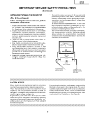
... two clip leads, connect a 1.5k ohm, 10 watt resistor paralleled by using replacement components replacement parts shown in the Replacement Parts Lists and 111S222c333h444e555m666777a888ti999c000D111222ia333g444r555a666m777s888.999000111222333444555666777888999000111222111222333444555666777888999000111222333444555666777888999000111222333444555666777888999000111222111222333444555666777888999000111222333444555666777888999000111222333444555666777888999000111222111222 3 32F630 32F631 IMPORTANT SERVICE SAFETY PRECAUTION (Continued) BEFORE RETURNING THE RECEIVER (Fire & Shock Hazard) Before...
... two clip leads, connect a 1.5k ohm, 10 watt resistor paralleled by using replacement components replacement parts shown in the Replacement Parts Lists and 111S222c333h444e555m666777a888ti999c000D111222ia333g444r555a666m777s888.999000111222333444555666777888999000111222111222333444555666777888999000111222333444555666777888999000111222333444555666777888999000111222111222333444555666777888999000111222333444555666777888999000111222333444555666777888999000111222111222 3 32F630 32F631 IMPORTANT SERVICE SAFETY PRECAUTION (Continued) BEFORE RETURNING THE RECEIVER (Fire & Shock Hazard) Before...

Service Manual
Page 10
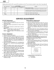
...in figure "A" and "B" as below respectively. • COMPONENT INPUT 3. Screen Adjustment 1. Reset the master screen control to "01", this step, if you selected a B/W picture ...green and "V48" blue is adjusted to compensate for characteristics of parts Holding down both the VOL-up and CH-up buttons on the TV set in figure "A" and "B" as below respectively. Set the... data to come out of "V09" and "V10" respectively. 5. 32F630 32F631 Holding down both the VOL-up and CH-up buttons on the TV set at low brightness level. 6. AB LUMINESCENCE CONFIRMATION A: 95±...
...in figure "A" and "B" as below respectively. • COMPONENT INPUT 3. Screen Adjustment 1. Reset the master screen control to "01", this step, if you selected a B/W picture ...green and "V48" blue is adjusted to compensate for characteristics of parts Holding down both the VOL-up and CH-up buttons on the TV set in figure "A" and "B" as below respectively. Set the... data to come out of "V09" and "V10" respectively. 5. 32F630 32F631 Holding down both the VOL-up and CH-up buttons on the TV set at low brightness level. 6. AB LUMINESCENCE CONFIRMATION A: 95±...
Service Manual
Page 11
...95±10cd/m2 B: 1.5±0.5cd/m2 10 SERVICE ADJUSTMENT RF AGC Adjustment 1. Screen Adjustment 1. Adjust the master screen control until a good grey scale with normal whites at service mode for more than 2 seconds will PART REPLACED IC2001 IC201 IC2101 CRT IC3001 ADJUSTMENT NECESSARY UNNECESSARY X X X X X NOTES Data...a black raster. Note 2 : Setting the data to point where no noise or beat appears. 32F630 32F631 Holding down both the VOL-up and CH-up buttons on the TV set at low brightness level. 6. Enter the service mode and select the service adjustment "V03" ...
...95±10cd/m2 B: 1.5±0.5cd/m2 10 SERVICE ADJUSTMENT RF AGC Adjustment 1. Screen Adjustment 1. Adjust the master screen control until a good grey scale with normal whites at service mode for more than 2 seconds will PART REPLACED IC2001 IC201 IC2101 CRT IC3001 ADJUSTMENT NECESSARY UNNECESSARY X X X X X NOTES Data...a black raster. Note 2 : Setting the data to point where no noise or beat appears. 32F630 32F631 Holding down both the VOL-up and CH-up buttons on the TV set at low brightness level. 6. Enter the service mode and select the service adjustment "V03" ...
Service Manual
Page 18
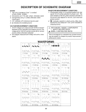
... of resistance "ohm" is a standard one, printed circuits may be subject to chassis ground.) å AND SHADED ( ) COMPONENTS = SAFETY RELATED PARTS. ç MARK= X-RAY RELATED PARTS. The wave shapes at 120V AC and all controls set for proper color. VOLTAGE MEASUREMENT CONDITIONS: 1. Photographs taken on the tint, color level...µ V B & W or Color signal. indicates waveform check points (See chart, waveforms are 1/16 watt, unless otherwise noted. 3. WAVEFORMS 17 WAVEFORM MEASUREMENT CONDITIONS: 1. 32F630 32F631 DESCRIPTION OF SCHEMATIC DIAGRAM NOTES: 1.
... of resistance "ohm" is a standard one, printed circuits may be subject to chassis ground.) å AND SHADED ( ) COMPONENTS = SAFETY RELATED PARTS. ç MARK= X-RAY RELATED PARTS. The wave shapes at 120V AC and all controls set for proper color. VOLTAGE MEASUREMENT CONDITIONS: 1. Photographs taken on the tint, color level...µ V B & W or Color signal. indicates waveform check points (See chart, waveforms are 1/16 watt, unless otherwise noted. 3. WAVEFORMS 17 WAVEFORM MEASUREMENT CONDITIONS: 1. 32F630 32F631 DESCRIPTION OF SCHEMATIC DIAGRAM NOTES: 1.
Service Manual
Page 32
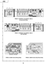
32F630 32F631 H G PWB-F: CONTROL Unit(32F631 ONLY) (Component Side) F E PWB-F: CONTROL Unit(32F631 ONLY) (Wiring Side) D C B A PWB-S: AUDIO Unit (Wiring Side) PWB-S: AUDIO Unit (Chip Parts Side) 1 2 3 4 5 6 38
32F630 32F631 H G PWB-F: CONTROL Unit(32F631 ONLY) (Component Side) F E PWB-F: CONTROL Unit(32F631 ONLY) (Wiring Side) D C B A PWB-S: AUDIO Unit (Wiring Side) PWB-S: AUDIO Unit (Chip Parts Side) 1 2 3 4 5 6 38
Service Manual
Page 33
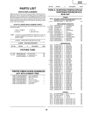
... 32F630 32F631 Ref. For location of a substitute replacement part which have these special safety characteristics identified in the Replacement Parts Lists and Schematic Diagrams. The use of SHARP Parts Distributor, Please call Toll-Free; 1800-BE-SHARP 5 MARK: SPARE PARTS-DELIVERY SECTION ' MARK: X-RAY RELATED PARTS Ref. PWB-A DUNTKB567WEX8 - CRT Unit - Control Unit(32F631) - Part No. 5 Description Code PARTS LIST PARTS...
... 32F630 32F631 Ref. For location of a substitute replacement part which have these special safety characteristics identified in the Replacement Parts Lists and Schematic Diagrams. The use of SHARP Parts Distributor, Please call Toll-Free; 1800-BE-SHARP 5 MARK: SPARE PARTS-DELIVERY SECTION ' MARK: X-RAY RELATED PARTS Ref. PWB-A DUNTKB567WEX8 - CRT Unit - Control Unit(32F631) - Part No. 5 Description Code PARTS LIST PARTS...
Service Manual
Page 38
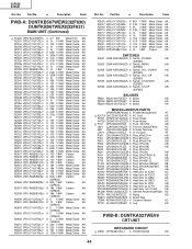
... CF2040 RCRM-0003CEZZ+ X Ceramic Vibrator AC TP701 QLUGP0102PEZZ X Lug AA PWB-B: DUNTKA527WEV9 CRT UNIT INTEGRATED CIRCUIT å IC850 VHiTDA6103Q-1 X TDA6103Q/N3 AG 44 Part No. 5 Description Code PWB-A: DUNTKB567WEW2(32F630) DUNTKB567WEX8(32F631) MAIN UNIT (Continued) å R1420 VRN-RL3LB2R7J+ X 2.7 3W Metal Film AB R2001 VRS-CY1JF102J∗ X 1k 1/16W Metal Oxide AA...
... CF2040 RCRM-0003CEZZ+ X Ceramic Vibrator AC TP701 QLUGP0102PEZZ X Lug AA PWB-B: DUNTKA527WEV9 CRT UNIT INTEGRATED CIRCUIT å IC850 VHiTDA6103Q-1 X TDA6103Q/N3 AG 44 Part No. 5 Description Code PWB-A: DUNTKB567WEW2(32F630) DUNTKB567WEX8(32F631) MAIN UNIT (Continued) å R1420 VRN-RL3LB2R7J+ X 2.7 3W Metal Film AB R2001 VRS-CY1JF102J∗ X 1k 1/16W Metal Oxide AA...
Service Manual
Page 42
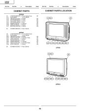
... HiNDPA433WJSA X Indicator HDECQ0104GJKA X Decration Plate JBTN-0129GJKA X Button 2B GCABB0160GJKB X Rear Cabinet Code Ref. Part No. 5 Description CABINET PARTS 1A 1A-1 1A-2 1A-3 1A-4 1A-5 1A-6 1A-8 1A-7 32F630 CCABAA208WEH0 X Front Cabinet Ass'y Not Available - Part No. 5 Description Code CABINET PARTS LOCATION BF AD 1A 1A-1 2A AC AD AE AC AC AB AD AF...
... HiNDPA433WJSA X Indicator HDECQ0104GJKA X Decration Plate JBTN-0129GJKA X Button 2B GCABB0160GJKB X Rear Cabinet Code Ref. Part No. 5 Description CABINET PARTS 1A 1A-1 1A-2 1A-3 1A-4 1A-5 1A-6 1A-8 1A-7 32F630 CCABAA208WEH0 X Front Cabinet Ass'y Not Available - Part No. 5 Description Code CABINET PARTS LOCATION BF AD 1A 1A-1 2A AC AD AE AC AC AB AD AF...

Service Manual
Page 44
No part of this publication may be reproduced, stored in a retrieval system, or transmitted in Japan In Japan gedruckt Design and Production Information Design : JAPAN Production : SEMEX MY. 32F630 32F631 COPYRIGHT © 2003 BY SHARP CORPORATION ALL RIGHTS RESERVED. TQ1492-S Apr. 2003 Printed in any form or by any means, electronic, mechanical, photocopying, recording, or otherwise, without prior written permission of the publisher. DS SHARP CORPORATION AV Systems Group Quality & Reliability Control Center Yaita, Tochigi 329-2193, Japan
No part of this publication may be reproduced, stored in a retrieval system, or transmitted in Japan In Japan gedruckt Design and Production Information Design : JAPAN Production : SEMEX MY. 32F630 32F631 COPYRIGHT © 2003 BY SHARP CORPORATION ALL RIGHTS RESERVED. TQ1492-S Apr. 2003 Printed in any form or by any means, electronic, mechanical, photocopying, recording, or otherwise, without prior written permission of the publisher. DS SHARP CORPORATION AV Systems Group Quality & Reliability Control Center Yaita, Tochigi 329-2193, Japan