
Instructions for Use
Page 48
... years. front view (SR 350 IEM G2 twin transmitter 6 Stereo transmitter - Contents Important safety instructions 2 The ew 300 IEM G2 systems 4 The channel bank system 5 Delivery includes ...5 Overview of the graphic display (transmitter only 32 Stereo/mono selection (transmitter only 33 Activating/deactivating the lock ...Specifications ...38 Connector assignment 39 Accessories and spare parts 40 Manufacturer Declarations 41 Thank you for choosing Sennheiser! We have made Sennheiser a world-leading company in this product to be stored in the design and manufacture of high-...
... years. front view (SR 350 IEM G2 twin transmitter 6 Stereo transmitter - Contents Important safety instructions 2 The ew 300 IEM G2 systems 4 The channel bank system 5 Delivery includes ...5 Overview of the graphic display (transmitter only 32 Stereo/mono selection (transmitter only 33 Activating/deactivating the lock ...Specifications ...38 Connector assignment 39 Accessories and spare parts 40 Manufacturer Declarations 41 Thank you for choosing Sennheiser! We have made Sennheiser a world-leading company in this product to be stored in the design and manufacture of high-...
Instructions for Use
Page 50
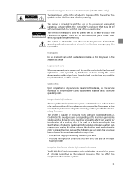
...replacement parts specified by law (in some countries) allowed to high transmission power The SR 350 IEM G2 twin transmitter can hear ringing or whistling sounds in order to the rear of the transmitter. This symbol is intended to alert the user to qualified personnel only. Refer servicing to ... of the transmitter (SR 350 IEM G2 only) The label shown on the left is attached to prevent hearing damage. This system is capable of producing sound pressure exceeding 85 dB(A). 85 dB(A) is the sound pressure corresponding to the maximum permissible volume which is by Sennheiser or those ...
...replacement parts specified by law (in some countries) allowed to high transmission power The SR 350 IEM G2 twin transmitter can hear ringing or whistling sounds in order to the rear of the transmitter. This symbol is intended to alert the user to qualified personnel only. Refer servicing to ... of the transmitter (SR 350 IEM G2 only) The label shown on the left is attached to prevent hearing damage. This system is capable of producing sound pressure exceeding 85 dB(A). 85 dB(A) is the sound pressure corresponding to the maximum permissible volume which is by Sennheiser or those ...
Instructions for Use
Page 51
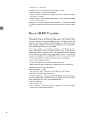
...of operational reliability and ease of use. The ew 300 IEM series offers two systems: y the ew 300 IEM G2 system (SR 300 IEM G2 stereo transmitter, EK 300 IEM G2 stereo receiver) y and the SR 350 IEM G2 twin transmitter The EK 300 IEM G2 can directly monitor the received sound signals without ...purposes, y having read these instructions, or under varying transmission conditions. 4 The ew 300 IEM G2 systems With the Sennheiser evolution wireless in this instruction manual. The transmitters and the receiver permit wireless transmission with studio-quality sound. can also be transmitted....
...of operational reliability and ease of use. The ew 300 IEM series offers two systems: y the ew 300 IEM G2 system (SR 300 IEM G2 stereo transmitter, EK 300 IEM G2 stereo receiver) y and the SR 350 IEM G2 twin transmitter The EK 300 IEM G2 can directly monitor the received sound signals without ...purposes, y having read these instructions, or under varying transmission conditions. 4 The ew 300 IEM G2 systems With the Sennheiser evolution wireless in this instruction manual. The transmitters and the receiver permit wireless transmission with studio-quality sound. can also be transmitted....
Instructions for Use
Page 52
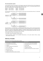
... Delivery includes Depending on page 39). Your Sennheiser agent will have nine channel banks with 1440 transmission/receiving frequencies per frequency range. The channel bank system The ew 300 IEM G2 systems are available in six UHF frequency ranges...see "Type approvals" on the purchased system, delivery includes: ew 300 IEM G2 system y 1 EK 300 IEM G2 stereo receiver y 1 SR 300 IEM G2 stereo transmitter y 2 batteries y 1 telescopic antenna for SR 300 IEM G2 y 1 NT 2-1 mains unit y 1 pair of the ew 300 IEM G2 systems have all the necessary details on the preset channels without...
... Delivery includes Depending on page 39). Your Sennheiser agent will have nine channel banks with 1440 transmission/receiving frequencies per frequency range. The channel bank system The ew 300 IEM G2 systems are available in six UHF frequency ranges...see "Type approvals" on the purchased system, delivery includes: ew 300 IEM G2 system y 1 EK 300 IEM G2 stereo receiver y 1 SR 300 IEM G2 stereo transmitter y 2 batteries y 1 telescopic antenna for SR 300 IEM G2 y 1 NT 2-1 mains unit y 1 pair of the ew 300 IEM G2 systems have all the necessary details on the preset channels without...
Instructions for Use
Page 53
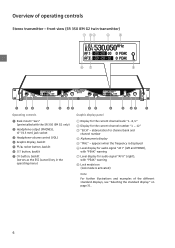
appears when the frequency is activated) Note: For further illustrations and examples of operating controls Stereo transmitter - abbreviation for the current channel number "1 ... 12" ቤ "B.CH" - front view (SR 350 IEM G2 twin transmitter) ቧቨ ቩ ³ ·» ¿ ´ ²¶ ·..."AF I" (left and MONO), with "PEAK" warning ቨ Level display for audio signal "AF II" (right), with the SR 350 IEM G2 only) · Headphone output (PHONES), ¼" (6.3 mm) jack socket » Headphone volume control (VOL) ¿ Graphic display, backlit ...
appears when the frequency is activated) Note: For further illustrations and examples of operating controls Stereo transmitter - abbreviation for the current channel number "1 ... 12" ቤ "B.CH" - front view (SR 350 IEM G2 twin transmitter) ቧቨ ቩ ³ ·» ¿ ´ ²¶ ·..."AF I" (left and MONO), with "PEAK" warning ቨ Level display for audio signal "AF II" (right), with the SR 350 IEM G2 only) · Headphone output (PHONES), ¼" (6.3 mm) jack socket » Headphone volume control (VOL) ¿ Graphic display, backlit ...
Instructions for Use
Page 54
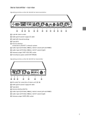
...), XLR-3F socket (right) ƺ Antenna output (ANT A/B), BNC socket ƻ Transmission power switch (RF POWER) Operating controls on the SR 350 IEM G2 twin transmitter º ¾µ ¸ º 3-pin IEC mains socket ¾ Cable grip for power supply DC cable ¸ Type plate ¹...441; Audio input (AF IN BAL/UNBAL), XLR-3F socket (right) ƺ Antenna output (ANT), BNC socket 7 rear view Operating controls on the SR 300 IEM G2 transmitter ¾º Ƹ ƹ¹ ¸ ƺ º DC socket for connection of mains unit (DC IN) ¾ Cable grip for ...
...), XLR-3F socket (right) ƺ Antenna output (ANT A/B), BNC socket ƻ Transmission power switch (RF POWER) Operating controls on the SR 350 IEM G2 twin transmitter º ¾µ ¸ º 3-pin IEC mains socket ¾ Cable grip for power supply DC cable ¸ Type plate ¹...441; Audio input (AF IN BAL/UNBAL), XLR-3F socket (right) ƺ Antenna output (ANT), BNC socket 7 rear view Operating controls on the SR 300 IEM G2 transmitter ¾º Ƹ ƹ¹ ¸ ƺ º DC socket for connection of mains unit (DC IN) ¾ Cable grip for ...
Instructions for Use
Page 56
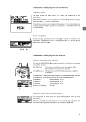
...772; button ᕤ are /the BA 2015 accupack is overmodulated frequently or for audio signal "AF" shows the modulation of the transmitter. When the transmitter is going flat » (LOW BAT)! In addition, the 4-step battery status display ብ on the display panel provides ...% 2 segments: capacity approx. 70 % 1 segment: capacity approx. 30 % Battery icon flashing: LOW BAT ብ Modulation display of the received transmitter The level display for an extended period of the batteries/BA 2015 accupack is excessively high, the level display for audio signal "AF" shows full...
...772; button ᕤ are /the BA 2015 accupack is overmodulated frequently or for audio signal "AF" shows the modulation of the transmitter. When the transmitter is going flat » (LOW BAT)! In addition, the 4-step battery status display ብ on the display panel provides ...% 2 segments: capacity approx. 70 % 1 segment: capacity approx. 30 % Battery icon flashing: LOW BAT ብ Modulation display of the received transmitter The level display for an extended period of the batteries/BA 2015 accupack is excessively high, the level display for audio signal "AF" shows full...

Instructions for Use
Page 57
... remains backlit for approx. 15 seconds. 10 "MUTE" display The "MUTE" display ቨ appears on the display panel when the RF signal of the received transmitter is too weak. ቨ "PILOT" display The "PILOT" display ቧ appears on the display panel when the pilot tone evaluation is activated (see "Activating/...green LED (RF) ᕤ at the front of the receiver lights up when the audio output is muted because y the RF signal of the received transmitter is too weak, ¿ y the transmitter is set to mono operation and the receiver's pilot tone evaluation is being received.
... remains backlit for approx. 15 seconds. 10 "MUTE" display The "MUTE" display ቨ appears on the display panel when the RF signal of the received transmitter is too weak. ቨ "PILOT" display The "PILOT" display ቧ appears on the display panel when the pilot tone evaluation is activated (see "Activating/...green LED (RF) ᕤ at the front of the receiver lights up when the audio output is muted because y the RF signal of the received transmitter is too weak, ¿ y the transmitter is set to mono operation and the receiver's pilot tone evaluation is being received.
Instructions for Use
Page 58
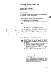
...severely unbalanced rack. ̈ When connecting the device to affect the ventilation required for use SR 300 IEM G2 transmitter/ SR 350 IEM G2 twin transmitter Fitting the device feet To ensure that the transmitter cannot slip on the surface on the left. Note: Do not fit the rubber feet when rack... mounting the transmitter. If necessary, provide overcurrent protection. ̈ Ensure a reliable mains ground connection of ...
...severely unbalanced rack. ̈ When connecting the device to affect the ventilation required for use SR 300 IEM G2 transmitter/ SR 350 IEM G2 twin transmitter Fitting the device feet To ensure that the transmitter cannot slip on the surface on the left. Note: Do not fit the rubber feet when rack... mounting the transmitter. If necessary, provide overcurrent protection. ̈ Ensure a reliable mains ground connection of ...

Instructions for Use
Page 59
... 300 IEM G2 For mounting one or two transmitters into the 19'' rack. ̈ Secure the rack mount "ears" to the rack using two of the supplied recessed head screws (M 3x6) respectively. ̈ Slide the transmitters into the 19" rack. ̈ Secure the rack mount "ears" to the twin transmitter...; to the front panels of the transmitters. ̈ Secure the rack mount "ears" to the transmitters using four screws (not included). Rack mounting the SR 350 IEM G2 The rack mount "ears" are already fitted to the rack. 12 twin transmitter To mount the twin transmitter into a 19'' rack: ̈...
... 300 IEM G2 For mounting one or two transmitters into the 19'' rack. ̈ Secure the rack mount "ears" to the rack using two of the supplied recessed head screws (M 3x6) respectively. ̈ Slide the transmitters into the 19" rack. ̈ Secure the rack mount "ears" to the twin transmitter...; to the front panels of the transmitters. ̈ Secure the rack mount "ears" to the transmitters using four screws (not included). Rack mounting the SR 350 IEM G2 The rack mount "ears" are already fitted to the rack. 12 twin transmitter To mount the twin transmitter into a 19'' rack: ̈...

Instructions for Use
Page 60
... as an accessory) when the transmitter position is to one SR 350 IEM G2 twin transmitter into the holes of the rack. Use the antenna mount matching the respective transmitter: y For the SR 300 IEM G2 transmitter: AM 2 antenna mount y For the SR 350 IEM G2 twin transmitter: GA 3030 AM antenna mount... 13 To mount only one transmitter into a rack: ƽ ƿ Ƽ Ƽ ̈ Hook...
... as an accessory) when the transmitter position is to one SR 350 IEM G2 twin transmitter into the holes of the rack. Use the antenna mount matching the respective transmitter: y For the SR 300 IEM G2 transmitter: AM 2 antenna mount y For the SR 350 IEM G2 twin transmitter: GA 3030 AM antenna mount... 13 To mount only one transmitter into a rack: ƽ ƿ Ƽ Ƽ ̈ Hook...

Instructions for Use
Page 61
... the supplied washers and nuts. ̈ Secure the antenna holders to the handles of the twin transmitter using two of the BNC extension cables to the blanking plate ƽ using the supplied washer and...the end cap to BNC connector ) To front mount the antenna of the SR 300 IEM G2 transmitter: ƽ ̈ Screw the BNC socket of the supplied screws respectively. 14 To front mount the antennas ...of the SR 350 IEM G2 twin transmitter: ³ ̈ Unsecure the rack mount "ears" ³ from the rack. ̈...
... the supplied washers and nuts. ̈ Secure the antenna holders to the handles of the twin transmitter using two of the BNC extension cables to the blanking plate ƽ using the supplied washer and...the end cap to BNC connector ) To front mount the antenna of the SR 300 IEM G2 transmitter: ƽ ̈ Screw the BNC socket of the supplied screws respectively. 14 To front mount the antennas ...of the SR 350 IEM G2 twin transmitter: ³ ̈ Unsecure the rack mount "ears" ³ from the rack. ̈...
Instructions for Use
Page 62
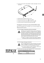
...transmission power (SR 350 IEM G2 only) With the SR 350 IEM G2 twin transmitter, you could interfere with other transmitters. ATTENTION! Danger of interference with other transmitters! Due to the high transmission power (100 mW) in the switch position "STANDARD", the optional AC 2 transmitter combiner must not be valid... (see "Accessories and spare parts" on frequency and/or transmission power usage require this. Depending on the twin transmitter. ̈ Slide the twin transmitter into the 19'' rack. ̈ Resecure the rack mount "ears" ³ to the rack ³. ̈ Connect ...
...transmission power (SR 350 IEM G2 only) With the SR 350 IEM G2 twin transmitter, you could interfere with other transmitters. ATTENTION! Danger of interference with other transmitters! Due to the high transmission power (100 mW) in the switch position "STANDARD", the optional AC 2 transmitter combiner must not be valid... (see "Accessories and spare parts" on frequency and/or transmission power usage require this. Depending on the twin transmitter. ̈ Slide the twin transmitter into the 19'' rack. ̈ Resecure the rack mount "ears" ³ to the rack ³. ̈ Connect ...

Instructions for Use
Page 63
... the device. ̈ Use the supplied mains cable to connect the receiver to the mains (100 to XLR-3F socket Ƹ. To disconnect the transmitter from the mains: ̈ Pull out the mains connector from the wall socket. Ƹƹ Connecting the amplifier/mixing console ̈ Connect the... operation must be connected to 240 V AC, 50 or 60 Hz). ̈ Ensure a reliable mains ground connection of hearing damage! To connect the transmitter to the mains: ̈ Pass the cable through the cable grip ¾. ̈ Connect the supplied mains cable to electric current! If you are...
... the device. ̈ Use the supplied mains cable to connect the receiver to the mains (100 to XLR-3F socket Ƹ. To disconnect the transmitter from the mains: ̈ Pull out the mains connector from the wall socket. Ƹƹ Connecting the amplifier/mixing console ̈ Connect the... operation must be connected to 240 V AC, 50 or 60 Hz). ̈ Ensure a reliable mains ground connection of hearing damage! To connect the transmitter to the mains: ̈ Pass the cable through the cable grip ¾. ̈ Connect the supplied mains cable to electric current! If you are...
Instructions for Use
Page 64
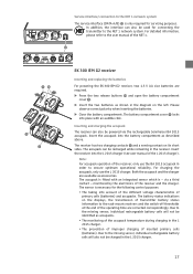
...and accupacks. The accupack is fitted with an audible click. The battery status indications on the displays, the transmission of transmitter battery status information to the rack-mount receivers and the switch-off thresholds at the end of the accupack temperature during...into the battery compartment as accupacks. via the rechargeable Sennheiser BA 2015 accupack. Note: For accupack operation of the NET 1. ¹ ¾µ ¾ ´ EK 300 IEM G2 receiver Inserting and replacing the batteries For powering the EK 300 IEM G2 receiver, two 1.5 V AA size batteries are required....
...and accupacks. The accupack is fitted with an audible click. The battery status indications on the displays, the transmission of transmitter battery status information to the rack-mount receivers and the switch-off thresholds at the end of the accupack temperature during...into the battery compartment as accupacks. via the rechargeable Sennheiser BA 2015 accupack. Note: For accupack operation of the NET 1. ¹ ¾µ ¾ ´ EK 300 IEM G2 receiver Inserting and replacing the batteries For powering the EK 300 IEM G2 receiver, two 1.5 V AA size batteries are required....
Instructions for Use
Page 65
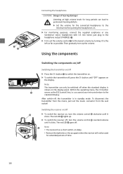
...components on/off . » Note: y The receiver has a short switch-on . ̈ For monitoring purposes, connect the supplied earphones or any Sennheiser stereo headphones with 3.5 mm stereo jack plug to the headphone output (PHONES) ³. ̈ First, set the volume control · to the ...standard display. The red LED » goes off Switching the transmitter on the display panel. To disconnect the transmitter from the mains, pull out the mains connector from the wall socket! y Remove the batteries or the accupack when the...
...components on/off . » Note: y The receiver has a short switch-on . ̈ For monitoring purposes, connect the supplied earphones or any Sennheiser stereo headphones with 3.5 mm stereo jack plug to the headphone output (PHONES) ³. ̈ First, set the volume control · to the ...standard display. The red LED » goes off Switching the transmitter on the display panel. To disconnect the transmitter from the mains, pull out the mains connector from the wall socket! y Remove the batteries or the accupack when the...

Instructions for Use
Page 66
...; Ƹ Adjusting the volume CAUTION! and provided that the standard display is shown on page 30). ᕧ SR 300 IEM G2/SR 350 IEM G2 Activating/deactivating the lock mode Transmitter and receiver have a lock mode that y the transmitter is accidentally programmed or switched off during operation, y the balance setting is attached to adjust the relative levels...
...; Ƹ Adjusting the volume CAUTION! and provided that the standard display is shown on page 30). ᕧ SR 300 IEM G2/SR 350 IEM G2 Activating/deactivating the lock mode Transmitter and receiver have a lock mode that y the transmitter is accidentally programmed or switched off during operation, y the balance setting is attached to adjust the relative levels...

Instructions for Use
Page 67
... selected menu Setting mode store the settings and return to the previous menu level ̆/̄ Standard display without function (transmitter) adjust the balance (receiver) Operating menu change to the previous menu (̆) or change to the standard display 20 ON... (transmitter only) Standard display switch the transmitter on stage or during a live show or presentation. The buttons Buttons Mode To ... The operating menu To ensure intuitive operation of the...
... selected menu Setting mode store the settings and return to the previous menu level ̆/̄ Standard display without function (transmitter) adjust the balance (receiver) Operating menu change to the previous menu (̆) or change to the standard display 20 ON... (transmitter only) Standard display switch the transmitter on stage or during a live show or presentation. The buttons Buttons Mode To ... The operating menu To ensure intuitive operation of the...
Instructions for Use
Page 68
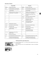
EK 300 IEM G2 21 Overview of menus Display Bank Channel Tune ⎯ Transmitter Function of the menu Display Switching between channel banks BANK Switching between the channels in a channel bank CHAN Setting a transmission frequency for the TUNE channel...Activating/deactivating the pilot tone evaluation ⎯ ⎯ Activating/deactivating the lock mode Exiting the operating menu and returning to the standard display SR 300 IEM G2/SR 350 IEM G2 Working with the operating menu By way of example of the "Tune" menu, this section describes how to use the operating menu. After ...
EK 300 IEM G2 21 Overview of menus Display Bank Channel Tune ⎯ Transmitter Function of the menu Display Switching between channel banks BANK Switching between the channels in a channel bank CHAN Setting a transmission frequency for the TUNE channel...Activating/deactivating the pilot tone evaluation ⎯ ⎯ Activating/deactivating the lock mode Exiting the operating menu and returning to the standard display SR 300 IEM G2/SR 350 IEM G2 Working with the operating menu By way of example of the "Tune" menu, this section describes how to use the operating menu. After ...

Instructions for Use
Page 69
... a setting ̈ Press the SET button to adjust the setting. With most menus, new settings become effective after they have entered the operating menu, the transmitter's ON button serves as the ESC (cancel) key, i.e. With the receiver, the new setting flashes on the display. With the... transmitter, the current setting is stored. An exception are displayed. When you cancel your entry. 22 Adjusting a setting ̈ Press the ̄/̆ rocker button to...
... a setting ̈ Press the SET button to adjust the setting. With most menus, new settings become effective after they have entered the operating menu, the transmitter's ON button serves as the ESC (cancel) key, i.e. With the receiver, the new setting flashes on the display. With the... transmitter, the current setting is stored. An exception are displayed. When you cancel your entry. 22 Adjusting a setting ̈ Press the ̄/̆ rocker button to...

