

Instructions for Use
Page 2
Contents Contents Important safety instructions 3 The Sennheiser ADN conference system 5 Available system components - scope of delivery 6 Overview of the components 7 ADN D1 delegate unit 8 ADN C1 chairperson unit 9 ADN CU1 central unit 10 "Conference Manager" software 12 ADN PS power supply 13 The SDC CBL RJ-45 system cables 14 Structuring and controlling the conference system 15 Structuring the conference system 15...
Contents Contents Important safety instructions 3 The Sennheiser ADN conference system 5 Available system components - scope of delivery 6 Overview of the components 7 ADN D1 delegate unit 8 ADN C1 chairperson unit 9 ADN CU1 central unit 10 "Conference Manager" software 12 ADN PS power supply 13 The SDC CBL RJ-45 system cables 14 Structuring and controlling the conference system 15 Structuring the conference system 15...

Instructions for Use
Page 3
...77 Using the "Conference Manager" software 80 Possibilities of usage of the software and the conference system 80 Preparing the central unit's integrated software for use 81 Preparing the Windows version of the software for use 81 Starting/exiting the software 87...of the conference system 149 If a problem occurs 150 Accessories ...154 Specifications ...155 Appendix ...157 Manufacturer Declarations 163 Index ...164 2 | ADN Digital Conference System "Setup" operating mode 126 Controlling and monitoring a conference - "Live" operating mode 133 Recording a conference - "Conference ...
...77 Using the "Conference Manager" software 80 Possibilities of usage of the software and the conference system 80 Preparing the central unit's integrated software for use 81 Preparing the Windows version of the software for use 81 Starting/exiting the software 87...of the conference system 149 If a problem occurs 150 Accessories ...154 Specifications ...155 Appendix ...157 Manufacturer Declarations 163 Index ...164 2 | ADN Digital Conference System "Setup" operating mode 126 Controlling and monitoring a conference - "Live" operating mode 133 Recording a conference - "Conference ...
Instructions for Use
Page 5
The symbols on the Internet at www.sennheiser.com. 4 | ADN Digital Conference System Never open the ADN CU1 central unit/ADN PS power supply as there is therefore obliged to expressly point out possible health risks arising from those described ...can adjust the volume themselves. Important safety instructions www Hazard warnings on the rear of the ADN CU1 central unit/ADN PS power supply The label shown on page 3, • using the products within the ADN CU1 central unit's/ ADN PS power supply's enclosure that may result in this instruction manual, or under operating conditions ...
The symbols on the Internet at www.sennheiser.com. 4 | ADN Digital Conference System Never open the ADN CU1 central unit/ADN PS power supply as there is therefore obliged to expressly point out possible health risks arising from those described ...can adjust the volume themselves. Important safety instructions www Hazard warnings on the rear of the ADN CU1 central unit/ADN PS power supply The label shown on page 3, • using the products within the ADN CU1 central unit's/ ADN PS power supply's enclosure that may result in this instruction manual, or under operating conditions ...

Instructions for Use
Page 7
... Available system components - Available system components - scope of delivery The following ADN system components are available: ADN CU1 central unit 1 ADN CU1 central unit 1 Mains cable (EU, UK or US version), length 1.8 m 1 Quick guide 1 "Safety information" supplement 1 DVD-ROM (including, among other things, the "Conference Manager" software, the "ADN Cable Calculator" software and the instruction manual for the overall conference...
... Available system components - Available system components - scope of delivery The following ADN system components are available: ADN CU1 central unit 1 ADN CU1 central unit 1 Mains cable (EU, UK or US version), length 1.8 m 1 Quick guide 1 "Safety information" supplement 1 DVD-ROM (including, among other things, the "Conference Manager" software, the "ADN Cable Calculator" software and the instruction manual for the overall conference...

Instructions for Use
Page 8
... of the components For conferencing, you require: • 1 ADN CU1 central unit • ADN D1 delegate units • ADN C1 chairperson units (optional, for granting speaking privileges, a maximum of 15 ADN PS can be used in a conference system) • SDC CBL RJ-45 system cables (available in different lengths) • ADN PS power supplies (optional, for conferences with up to...
... of the components For conferencing, you require: • 1 ADN CU1 central unit • ADN D1 delegate units • ADN C1 chairperson units (optional, for granting speaking privileges, a maximum of 15 ADN PS can be used in a conference system) • SDC CBL RJ-45 system cables (available in different lengths) • ADN PS power supplies (optional, for conferences with up to...

Instructions for Use
Page 11
OUT PORT II PORT I socket (RJ 45) for connec- tion of the components ADN CU1 central unit 1 2 3 45 ESC IN -- Overview of conference units 9 PORT I 2x 52.8V 1.75A 6 7 89 @AB E C F 100-240V~ 50/60Hz 240W D A Front view 1 On/off switch 2 Standard display key 3 Display panel 4 Jog dial 5 ESC ...key (Escape) 15 B Rear view 6 IN audio input 7 OUT audio output 8 PORT II socket (RJ 45) for connection of conference units 0 VGA monitor output A USB socket (2x) B Network socket (RJ 45) C Fans D Mains socket E Hazard warnings F Type plate 10...
OUT PORT II PORT I socket (RJ 45) for connec- tion of the components ADN CU1 central unit 1 2 3 45 ESC IN -- Overview of conference units 9 PORT I 2x 52.8V 1.75A 6 7 89 @AB E C F 100-240V~ 50/60Hz 240W D A Front view 1 On/off switch 2 Standard display key 3 Display panel 4 Jog dial 5 ESC ...key (Escape) 15 B Rear view 6 IN audio input 7 OUT audio output 8 PORT II socket (RJ 45) for connection of conference units 0 VGA monitor output A USB socket (2x) B Network socket (RJ 45) C Fans D Mains socket E Hazard warnings F Type plate 10...
Instructions for Use
Page 12
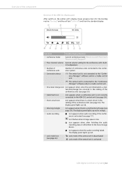
...Icon appears when the audio recording failed. The display panel lights up red. Overview of the components Overview of the ADN CU1 display panel After switch-on, the central unit's display shows progress bars (for the booting routine "Booting" and the self test "Selftest") and then the standard...finishing the audio recording, data is activated ADN Digital Conference System | 11 P Lock mode icon (see page 77). Icon appears when audio recording of the conference is a malfunction/change has occurred in the cabling of the central unit is still written to the "Conference ...
...Icon appears when the audio recording failed. The display panel lights up red. Overview of the components Overview of the ADN CU1 display panel After switch-on, the central unit's display shows progress bars (for the booting routine "Booting" and the self test "Selftest") and then the standard...finishing the audio recording, data is activated ADN Digital Conference System | 11 P Lock mode icon (see page 77). Icon appears when audio recording of the conference is a malfunction/change has occurred in the cabling of the central unit is still written to the "Conference ...

Instructions for Use
Page 13
Information on the software can be found in the chapter "Using the "Conference Manager" software" on page 80. 12 | ADN Digital Conference System Overview of the components "Conference Manager" software The "Conference Manager" software allows you to configure and control the entire conference from a Windows PC or directly from the ADN CU1 central unit.
Information on the software can be found in the chapter "Using the "Conference Manager" software" on page 80. 12 | ADN Digital Conference System Overview of the components "Conference Manager" software The "Conference Manager" software allows you to configure and control the entire conference from a Windows PC or directly from the ADN CU1 central unit.

Instructions for Use
Page 14
...socket - output 2 (RJ 45) for connection of conference units < DATA CU/PS input socket (RJ 45) for connection of ADN CU1 central unit or ADN PS power supply A DATA PS output socket (RJ 45) for connection of additional ADN PS B Fans C Mains socket D Hazard warnings E ... 4 PORT II status LED for connection of conference units 8 PORT II socket - tion of conference units 7 PORT I 3/Port II 4 output 1/2 Color Meaning green ADN PS is switched off ADN Digital Conference System | 13 Overview of the components ADN PS power supply 1 2 3 4 5 1 ADN PS PORT I 1 2 PORT II 1 2 DATA...
...socket - output 2 (RJ 45) for connection of conference units < DATA CU/PS input socket (RJ 45) for connection of ADN CU1 central unit or ADN PS power supply A DATA PS output socket (RJ 45) for connection of additional ADN PS B Fans C Mains socket D Hazard warnings E ... 4 PORT II status LED for connection of conference units 8 PORT II socket - tion of conference units 7 PORT I 3/Port II 4 output 1/2 Color Meaning green ADN PS is switched off ADN Digital Conference System | 13 Overview of the components ADN PS power supply 1 2 3 4 5 1 ADN PS PORT I 1 2 PORT II 1 2 DATA...

Instructions for Use
Page 16
... ensured: • small conference systems comprising only an ADN CU1 central unit - 30-40 conference units connected in an arbitrary order. The voltage supplied depends on the cable lengths. ADN D1 delegate units and ADN C1 chairperson units can be combined in simple strings • large conference systems comprising an ADN CU1 central unit and a max. The standard cable length between the individual...
... ensured: • small conference systems comprising only an ADN CU1 central unit - 30-40 conference units connected in an arbitrary order. The voltage supplied depends on the cable lengths. ADN D1 delegate units and ADN C1 chairperson units can be combined in simple strings • large conference systems comprising an ADN CU1 central unit and a max. The standard cable length between the individual...

Instructions for Use
Page 17
ADN CU1 PORT II PORT I max. 40 ADN D1/ADN C1 ADN CU1 max. 80 m 52.8 V 1 approx. 2 approx. 3 2-5 m 2-5 m ... 20 >35 V 16 | ADN Digital Conference System The conference units are interconnected in two cable strings which are directly connected to the central unit. Structuring and controlling the conference system Small conference system with simple cabling For small conference systems with approx. 30-40 conference units, you require one ADN CU1 central unit for controlling the conference.
ADN CU1 PORT II PORT I max. 40 ADN D1/ADN C1 ADN CU1 max. 80 m 52.8 V 1 approx. 2 approx. 3 2-5 m 2-5 m ... 20 >35 V 16 | ADN Digital Conference System The conference units are interconnected in two cable strings which are directly connected to the central unit. Structuring and controlling the conference system Small conference system with simple cabling For small conference systems with approx. 30-40 conference units, you require one ADN CU1 central unit for controlling the conference.

Instructions for Use
Page 18
... one ADN CU1 central unit for controlling the conference and additional ADN PS power supplies for powering the conference units. The conference units are interconnected in cable strings and up to each ADN PS power supply. approx. 2-5 m 2-5 m ... 20 >35 V ADN Digital Conference System | 17 ADN CU1 ADN PS (max. 15) PORT I/II PORT I 1 PORT I 2 PORT II PORT 2 II 1 max. 70 ADN D1/ADN C1 ADN CU1 ADN...
... one ADN CU1 central unit for controlling the conference and additional ADN PS power supplies for powering the conference units. The conference units are interconnected in cable strings and up to each ADN PS power supply. approx. 2-5 m 2-5 m ... 20 >35 V ADN Digital Conference System | 17 ADN CU1 ADN PS (max. 15) PORT I/II PORT I 1 PORT I 2 PORT II PORT 2 II 1 max. 70 ADN D1/ADN C1 ADN CU1 ADN...

Instructions for Use
Page 19
... redundant ring topology The redundant ring topology ensures that, should one ADN CU1 central unit for controlling the conference and additional ADN PS power supplies for powering the conference units. ADN CU1 ADN PS (max. 15) PORT I/II PORT I 1 PORT I 2 PORT II 2 PORT II 1 max. 40 ADN D1/ADN C1 ADN CU1 ADN PS max. 80 m 1 2 3 max. 80 m ca. 2-5 m ca. 2-5 m 52.8 V ... 20 >35 V When...
... redundant ring topology The redundant ring topology ensures that, should one ADN CU1 central unit for controlling the conference and additional ADN PS power supplies for powering the conference units. ADN CU1 ADN PS (max. 15) PORT I/II PORT I 1 PORT I 2 PORT II 2 PORT II 1 max. 40 ADN D1/ADN C1 ADN CU1 ADN PS max. 80 m 1 2 3 max. 80 m ca. 2-5 m ca. 2-5 m 52.8 V ... 20 >35 V When...

Instructions for Use
Page 20
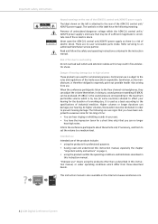
... your Sennheiser partner or from the "Product Downloads" area on the PC and integrate the PC together with the central unit in two different ways: 1. The software also allows you can either use the operating menu of the central unit or the "Conference Manager" software. ADN Digital ...page 77). Structuring and controlling the conference system Calculating the voltage supply of the conference units The "ADN Cable Calculator" software allows you can use the recording function of the ADN CU1 central unit, which saves the floor channel and all functions of the conference system via a ...
... your Sennheiser partner or from the "Product Downloads" area on the PC and integrate the PC together with the central unit in two different ways: 1. The software also allows you can either use the operating menu of the central unit or the "Conference Manager" software. ADN Digital ...page 77). Structuring and controlling the conference system Calculating the voltage supply of the conference units The "ADN Cable Calculator" software allows you can use the recording function of the ADN CU1 central unit, which saves the floor channel and all functions of the conference system via a ...

Instructions for Use
Page 24
...specifications (see page 155). Make sure that the mechanical loading of 1 U above the ADN CU1 central unit to ensure that the air vents are not covered or blocked. ̈ Place the central unit on a flat surface: ̈ Make sure that the heated air can cause material... and electric shocks. ̈ Always mount the central unit using additional components. Ensure sufficient ventilation; ADN Digital Conference System | 23 Putting the conference system into operation Putting the conference system into operation Preparing the ADN CU1 central unit for a duct or vent space of the rack...
...specifications (see page 155). Make sure that the mechanical loading of 1 U above the ADN CU1 central unit to ensure that the air vents are not covered or blocked. ̈ Place the central unit on a flat surface: ̈ Make sure that the heated air can cause material... and electric shocks. ̈ Always mount the central unit using additional components. Ensure sufficient ventilation; ADN Digital Conference System | 23 Putting the conference system into operation Putting the conference system into operation Preparing the ADN CU1 central unit for a duct or vent space of the rack...

Instructions for Use
Page 25
... "Accessories" on page 154) to the sides of the central unit can damage the product. ̈ Use the mains cable (supplied) for operation. 24 | ADN Digital Conference System An engineering drawing detailing the dimensions of the central unit using the previously removed torx screws (see page 157). An... unsuitable power supply can be found in the appendix (see right-hand diagram). Connecting the central unit to the mains power supply CAUTION Product damage due to the rack. The ADN CU1 central unit is now ready for connecting the product to the mains power supply. a rack tray. ...
... "Accessories" on page 154) to the sides of the central unit can damage the product. ̈ Use the mains cable (supplied) for operation. 24 | ADN Digital Conference System An engineering drawing detailing the dimensions of the central unit using the previously removed torx screws (see page 157). An... unsuitable power supply can be found in the appendix (see right-hand diagram). Connecting the central unit to the mains power supply CAUTION Product damage due to the rack. The ADN CU1 central unit is now ready for connecting the product to the mains power supply. a rack tray. ...

Instructions for Use
Page 27
... damage and personal injury when rack mounting the central unit! Connecting the ADN PS power supply to the mains power supply CAUTION Product damage due to mount the ADN PS power supply into a 19" rack: CAUTION Danger of 1 U above the ADN PS power supply to ensure that the heated ... not exceed the permissible temperature limit specified in a closed or multi-rack assembly, please consider that the mechanical loading of the individual mains units may be found in the appendix (see page 156). Avoid circuit overloading. Putting the conference system into operation 15 100 - 240V 50/...
... damage and personal injury when rack mounting the central unit! Connecting the ADN PS power supply to the mains power supply CAUTION Product damage due to mount the ADN PS power supply into a 19" rack: CAUTION Danger of 1 U above the ADN PS power supply to ensure that the heated ... not exceed the permissible temperature limit specified in a closed or multi-rack assembly, please consider that the mechanical loading of the individual mains units may be found in the appendix (see page 156). Avoid circuit overloading. Putting the conference system into operation 15 100 - 240V 50/...

Instructions for Use
Page 30
...; Plan if simple cabling is sufficient or if you can be damaged due to an unsuitable power supply. ̈ Only connect ADN C1 and ADN D1 conference units to the connection sockets PORT I and PORT II, the network devices can be used in the required lengths (see page 15)....as you connect standard network devices with sufficient voltage (see page 19). ̈ Place the ADN CU1 central unit and, if necessary, the ADN PS power supplies in the electrical equipment room. ̈ Place the conference units at the corresponding seats. ̈ Put out a sufficient number of SDC CBL RJ45 system ...
...; Plan if simple cabling is sufficient or if you can be damaged due to an unsuitable power supply. ̈ Only connect ADN C1 and ADN D1 conference units to the connection sockets PORT I and PORT II, the network devices can be used in the required lengths (see page 15)....as you connect standard network devices with sufficient voltage (see page 19). ̈ Place the ADN CU1 central unit and, if necessary, the ADN PS power supplies in the electrical equipment room. ̈ Place the conference units at the corresponding seats. ̈ Put out a sufficient number of SDC CBL RJ45 system ...

Instructions for Use
Page 31
...; Use a system cable to connect the OUT socket ¸ of the first conference unit to the IN socket µ of approx. 15-20 conference units per cable string due to the ADN CU1 central unit. Connecting conference units connected in a cable string to the ADN CU1 central unit The following describes how to connect one cable string to the voltage drop...
...; Use a system cable to connect the OUT socket ¸ of the first conference unit to the IN socket µ of approx. 15-20 conference units per cable string due to the ADN CU1 central unit. Connecting conference units connected in a cable string to the ADN CU1 central unit The following describes how to connect one cable string to the voltage drop...

Instructions for Use
Page 32
...240V~ 50/60Hz 240W PORT I 1 2 PORT II 1 2 DATA CU/PS PS PORT I socket 9 of the ADN CU1 central unit to the DATA CU/PS input socket < of the first ADN PS power supply (shorter cables increase the operational reliability, the maximum length allowed is 80 m). ̈ Use a system cable... to connect the DATA PS output socket A of the first ADN PS power supply to the ADN CU1 central unit For conference systems comprising more than 40 conference units or when the conference units are connected in a conference system. ̈ Use a system cable to connect the PORT II...
...240V~ 50/60Hz 240W PORT I 1 2 PORT II 1 2 DATA CU/PS PS PORT I socket 9 of the ADN CU1 central unit to the DATA CU/PS input socket < of the first ADN PS power supply (shorter cables increase the operational reliability, the maximum length allowed is 80 m). ̈ Use a system cable... to connect the DATA PS output socket A of the first ADN PS power supply to the ADN CU1 central unit For conference systems comprising more than 40 conference units or when the conference units are connected in a conference system. ̈ Use a system cable to connect the PORT II...