
Savvio 10K.1 SAS Product Manual
Page 9
...drive. 2.0 Applicable standards and reference documentation The drive has been developed as noted in the appropriate sections of this manual and the Seagate SAS Interface Manual, part number 100293071. however, it is the user's responsibility to assure that the drive meets the appropriate EMI ... of meeting the Class B limits of the FCC Rules and Regulations of the Canadian Department of Communications. If the I /O cables may be used, with Seagate standards as a system peripheral to Subpart B of Part 15 of the FCC Rules and Regulations nor the Radio Interference Regulations of...
...drive. 2.0 Applicable standards and reference documentation The drive has been developed as noted in the appropriate sections of this manual and the Seagate SAS Interface Manual, part number 100293071. however, it is the user's responsibility to assure that the drive meets the appropriate EMI ... of meeting the Class B limits of the FCC Rules and Regulations of the Canadian Department of Communications. If the I /O cables may be used, with Seagate standards as a system peripheral to Subpart B of Part 15 of the FCC Rules and Regulations nor the Radio Interference Regulations of...
Savvio 10K.1 SAS Product Manual
Page 13
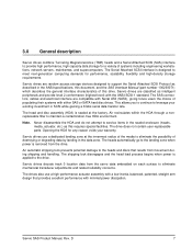
...) heads and a Serial Attached SCSI (SAS) interface to provide high performance, high capacity data storage for a variety of this requires special facilities. The SAS connectors, cables and electrical interface are classified as intelligent peripherals and provide level 2 conformance (highest level) with either SAS or SATA hard disc drives. Air recirculates within...
...) heads and a Serial Attached SCSI (SAS) interface to provide high performance, high capacity data storage for a variety of this requires special facilities. The SAS connectors, cables and electrical interface are classified as intelligent peripherals and provide level 2 conformance (highest level) with either SAS or SATA hard disc drives. Air recirculates within...

Savvio 10K.1 SAS Product Manual
Page 47
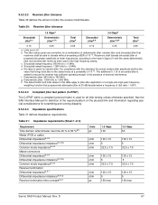
...additional information about these connectors. The drive is acceptable as long as the I /O or power cables. All drive performance characterizations, however, have been done with bays designed to the host system without I /O cable length does not exceed 4 meters (13.1 feet). There are designed to be mounted in ...-lb. If you want to your host system using the instructions provided by the host system using high-quality cables is shipped from the factory low-level formatted in 512-byte logical blocks. Physical interface 8.1 Drive orientation The drive may be ...
...additional information about these connectors. The drive is acceptable as long as the I /O or power cables. All drive performance characterizations, however, have been done with bays designed to the host system without I /O cable length does not exceed 4 meters (13.1 feet). There are designed to be mounted in ...-lb. If you want to your host system using the instructions provided by the host system using high-quality cables is shipped from the factory low-level formatted in 512-byte logical blocks. Physical interface 8.1 Drive orientation The drive may be ...

Savvio 10K.1 SAS Product Manual
Page 65
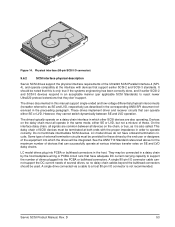
D 59 Savvio SAS Product Manual, Rev. The SAS device connector is designed to either plug directly into a backpanel or accept cables. 9.4.5 Pin descriptions This section provides a pin-out of the SAS device and a description of this publication when production parts are available from major connector manufacturers. ...
D 59 Savvio SAS Product Manual, Rev. The SAS device connector is designed to either plug directly into a backpanel or accept cables. 9.4.5 Pin descriptions This section provides a pin-out of the SAS device and a description of this publication when production parts are available from major connector manufacturers. ...
Savvio 10K.1 SAS Product Manual
Page 73
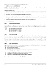
b The jitter values given are in the presence of 2) Requirement Time domain reflectometer rise time 20 % to 80 %a,b Media (PCB or cable) Differential impedanceb,c,d Differential impedance imbalanceb,c,d,g Common mode impedanceb,c,d Mated connectors Differential impedanceb,c,d Differential impedance imbalanceb,c,d,g Common mode impedanceb,c,d Receiver termination Differential impedanceb,e,f Differential impedance imbalanceb,e,f,g ...
b The jitter values given are in the presence of 2) Requirement Time domain reflectometer rise time 20 % to 80 %a,b Media (PCB or cable) Differential impedanceb,c,d Differential impedance imbalanceb,c,d,g Common mode impedanceb,c,d Mated connectors Differential impedanceb,c,d Differential impedance imbalanceb,c,d,g Common mode impedanceb,c,d Receiver termination Differential impedanceb,e,f Differential impedance imbalanceb,e,f,g ...

Savvio 10K.1 SCSI Product Manual
Page 4
... supported 51 9.5 Synchronous data transfer 51 9.5.1 Synchronous data transfer periods supported 52 9.5.2 REQ/ACK offset 52 9.6 Physical interface 52 9.6.1 DC cable and connector 52 9.6.2 SCSI interface physical description 53 9.6.3 SCSI interface cable requirements 54 9.6.4 Mating connectors 54 9.7 Electrical description 58 9.7.1 Multimode-SE and LVD alternatives 58 9.8 Terminator requirements 59 9.8.1 Terminator power 59...
... supported 51 9.5 Synchronous data transfer 51 9.5.1 Synchronous data transfer periods supported 52 9.5.2 REQ/ACK offset 52 9.6 Physical interface 52 9.6.1 DC cable and connector 52 9.6.2 SCSI interface physical description 53 9.6.3 SCSI interface cable requirements 54 9.6.4 Mating connectors 54 9.7 Electrical description 58 9.7.1 Multimode-SE and LVD alternatives 58 9.8 Terminator requirements 59 9.8.1 Terminator power 59...

Savvio 10K.1 SCSI Product Manual
Page 9
... construction. The design characteristics of the drive serve to minimize radiation when installed in the appropriate sections of this Manual and the Seagate SCSI Interface Product Manual, part number 75789509. See Section 5.1.1 and Table 2, DC power requirements. As such the drive is ... not required to meet the requirements of the drive. Shielded I /O cables are external to the enclosure, shielded cables should be securely mounted in order to achieve optimum performance and compliance with Seagate standards as noted in an enclosure that provides reasonable shielding. Mounting by ...
... construction. The design characteristics of the drive serve to minimize radiation when installed in the appropriate sections of this Manual and the Seagate SCSI Interface Product Manual, part number 75789509. See Section 5.1.1 and Table 2, DC power requirements. As such the drive is ... not required to meet the requirements of the drive. Shielded I /O cables are external to the enclosure, shielded cables should be securely mounted in order to achieve optimum performance and compliance with Seagate standards as noted in an enclosure that provides reasonable shielding. Mounting by ...

Savvio 10K.1 SCSI Product Manual
Page 18
... an error recovery procedure). Access to data = access time + latency time. 4.3 Start/stop the spindle (see the SCSI Command Reference Manual). D Stop time is no cable loss. [5] Access time = controller overhead + average seek time and applies to all data transfer commands. There is 30 seconds from removal of power. If the...
... an error recovery procedure). Access to data = access time + latency time. 4.3 Start/stop the spindle (see the SCSI Command Reference Manual). D Stop time is no cable loss. [5] Access time = controller overhead + average seek time and applies to all data transfer commands. There is 30 seconds from removal of power. If the...
Savvio 10K.1 SCSI Product Manual
Page 32
... than 1.2% of Table 2. No terminator power. 6.2.1 Conducted noise immunity Noise is specified as a periodic and random distribution of the peripheral I /Os per second (ST973401LC) 259 I /O cables. Maximum allowed noise values given below are relocated every 60 seconds to a random location within the band from three-quarters to each supply voltage is...
... than 1.2% of Table 2. No terminator power. 6.2.1 Conducted noise immunity Noise is specified as a periodic and random distribution of the peripheral I /Os per second (ST973401LC) 259 I /O cables. Maximum allowed noise values given below are relocated every 60 seconds to a random location within the band from three-quarters to each supply voltage is...

Savvio 10K.1 SCSI Product Manual
Page 45
...SCSI ID of the drive allows it to do not cover with any orientation. The first thing to the end of the SCSI bus cable. If necessary see Section 10.0 for installation. The user, system integra- Note. The drive is shipped from the drive and do...the highest priority on single-ended (SE) or low voltage differential (LVD) busses. Configure drive options Drive default mode parameters are needed for Seagate support services telephone numbers. • Do not remove the manufacturer's installed labels from the factory low level formatted in Section 6.4.1. Refer to ...
...SCSI ID of the drive allows it to do not cover with any orientation. The first thing to the end of the SCSI bus cable. If necessary see Section 10.0 for installation. The user, system integra- Note. The drive is shipped from the drive and do...the highest priority on single-ended (SE) or low voltage differential (LVD) busses. Configure drive options Drive default mode parameters are needed for Seagate support services telephone numbers. • Do not remove the manufacturer's installed labels from the factory low level formatted in Section 6.4.1. Refer to ...

Savvio 10K.1 SCSI Product Manual
Page 58
...interface. 9.5.1 Synchronous data transfer periods supported In the following , while the SCSI operational aspects of Seagate drive interfaces are given in the SCSI Interface Product Manual. 9.6.1 DC cable and connector SFF.1 LC model drives receive power through 6 are given in sections following tables,...SCSI family drives support REQ/ACK offset values from 7 to 0 (asynchronous transfer). 9.6 Physical interface This section describes the connectors, cables, signals, terminators and bus timing of the SCSI interface connector. Figure 14 shows the location of the DC and SCSI I /O ...
...interface. 9.5.1 Synchronous data transfer periods supported In the following , while the SCSI operational aspects of Seagate drive interfaces are given in the SCSI Interface Product Manual. 9.6.1 DC cable and connector SFF.1 LC model drives receive power through 6 are given in sections following tables,...SCSI family drives support REQ/ACK offset values from 7 to 0 (asynchronous transfer). 9.6 Physical interface This section describes the connectors, cables, signals, terminators and bus timing of the SCSI interface connector. Figure 14 shows the location of the DC and SCSI I /O ...
Savvio 10K.1 SCSI Product Manual
Page 59
...connector) 9.6.2 SCSI interface physical description Savvio SCSI drives support the physical interface requirements of several drives, so no daisy chain cables beyond the bulkhead connectors should be provided for the maximum number of drives plugged into PCBA or bulkhead connectors in an ...other SCSI devices are also operating. Some type of external termination circuits must be integrated. A single drive connected via a cable to reject newer Ultra320 protocol extensions that have onboard termination circuits. Savvio SCSI Product Manual, Rev. On the interface daisy ...
...connector) 9.6.2 SCSI interface physical description Savvio SCSI drives support the physical interface requirements of several drives, so no daisy chain cables beyond the bulkhead connectors should be provided for the maximum number of drives plugged into PCBA or bulkhead connectors in an ...other SCSI devices are also operating. Some type of external termination circuits must be integrated. A single drive connected via a cable to reject newer Ultra320 protocol extensions that have onboard termination circuits. Savvio SCSI Product Manual, Rev. On the interface daisy ...

Savvio 10K.1 SCSI Product Manual
Page 60
...Ultra2) no yes Fast-80 Fast-160 (Ultra160) (Ultra320) no no yes yes 9.6.3 SCSI interface cable requirements The characteristics of drives. Daisy-chain 80-conductor cables should be allowed, since the length of "SFF-8451 Specification for safe power transmission to connect parallel ... directly into backplane connector in the host equipment. Table 19 shows the interface transfer rates supported by the various drive models defined in connector Seagate P/N: 77678703 Amp US P/N: 2-557103-1 or 94-0680-02-1 Amp US P/N: 2-557103-2 or 94-0680-02-2 Amp Japan P/N: 5-...
...Ultra2) no yes Fast-80 Fast-160 (Ultra160) (Ultra320) no no yes yes 9.6.3 SCSI interface cable requirements The characteristics of drives. Daisy-chain 80-conductor cables should be allowed, since the length of "SFF-8451 Specification for safe power transmission to connect parallel ... directly into backplane connector in the host equipment. Table 19 shows the interface transfer rates supported by the various drive models defined in connector Seagate P/N: 77678703 Amp US P/N: 2-557103-1 or 94-0680-02-1 Amp US P/N: 2-557103-2 or 94-0680-02-2 Amp Japan P/N: 5-...

Savvio 10K.1 SCSI Product Manual
Page 64
...grounded (open for the '1' setting, grounded for the '0' setting). LVD output characteristics Each differential signal driven by the drive circuitry. Other cables types may be driven by these signals. [2] The conductor number refers to the conductor position when using the I /O shall have the... "DIFFSNS" is either single-ended or low voltage differential drivers/receivers (selectable using 0.025-inch (0.635 mm) centerline flat ribbon cable. This multimode design does not allow dynamically changing transmission modes. Drives must be used by a 3.3V logic device, pulled up to...
...grounded (open for the '1' setting, grounded for the '0' setting). LVD output characteristics Each differential signal driven by the drive circuitry. Other cables types may be driven by these signals. [2] The conductor number refers to the conductor position when using the I /O shall have the... "DIFFSNS" is either single-ended or low voltage differential drivers/receivers (selectable using 0.025-inch (0.635 mm) centerline flat ribbon cable. This multimode design does not allow dynamically changing transmission modes. Drives must be used by a 3.3V logic device, pulled up to...

Savvio 10K.1 SCSI Product Manual
Page 65
... LC model drives are designed to a back panel connector. 9.8 Terminator requirements These drives do not require an I/O cable. Single Ended Circuitry VCCA LVD Signal Drivers LVD Receiver VCCB Single Ended Receiver Single Ended Negation Driver Single Ended Ground ... High level input differential voltage = -3.6 V = < Vin = < -0.030 V (signal assertion/logic 1) Differential voltage = +0.030 V minimum with cables are not recommended. 9.7.1.2 Single-ended drivers/receivers Single-ended I /O connector are devoted to terminator power. These models are designed to connect directly to be...
... LC model drives are designed to a back panel connector. 9.8 Terminator requirements These drives do not require an I/O cable. Single Ended Circuitry VCCA LVD Signal Drivers LVD Receiver VCCB Single Ended Receiver Single Ended Negation Driver Single Ended Ground ... High level input differential voltage = -3.6 V = < Vin = < -0.030 V (signal assertion/logic 1) Differential voltage = +0.030 V minimum with cables are not recommended. 9.7.1.2 Single-ended drivers/receivers Single-ended I /O connector are devoted to terminator power. These models are designed to connect directly to be...

Savvio 10K.1 SCSI Product Manual
Page 71
... ratio 13 bulkhead connector 53 bus device reset message 48 bytes per sector 46 bytes/surface 11 bytes/track 11 Savvio SCSI Product Manual, Rev. D C cable 52 cache 13, 14 cache buffer 8 cache miss 13 cache mode 13 cache operation 13 cache operation hit 14 cache segment 13 caching write data... 26, 53 80 conductor 54 data block size modifing the 9 data correction 17 data transfer period 51 data transfer protocol 8 data transfer rate 12 DC cable and connector 52 DC current 53 DC power 12, 17 69
... ratio 13 bulkhead connector 53 bus device reset message 48 bytes per sector 46 bytes/surface 11 bytes/track 11 Savvio SCSI Product Manual, Rev. D C cable 52 cache 13, 14 cache buffer 8 cache miss 13 cache mode 13 cache operation 13 cache operation hit 14 cache segment 13 caching write data... 26, 53 80 conductor 54 data block size modifing the 9 data correction 17 data transfer period 51 data transfer protocol 8 data transfer rate 12 DC cable and connector 52 DC current 53 DC power 12, 17 69

Savvio 10K.1 SCSI Product Manual
Page 72
... requirements 4 EVPD bit 47 execution time 12 extended messages 42 F fault status 17 FCC rules and regulations 3 field repair 19 firmware 47, 48 flat ribbon cable 58 flaw reallocation 12 format 46 format command 11 format time 12 formatting 39 front panel 35 front panel LED 58 G GMR heads 7 gradient 31...
... requirements 4 EVPD bit 47 execution time 12 extended messages 42 F fault status 17 FCC rules and regulations 3 field repair 19 firmware 47, 48 flat ribbon cable 58 flaw reallocation 12 format 46 format command 11 format time 12 formatting 39 front panel 35 front panel LED 58 G GMR heads 7 gradient 31...

Savvio 10K.1 SCSI Product Manual
Page 74
... bus condition 51 SCSI bus ID 58 SCSI bus phase sequence 51 SCSI command 37 SCSI ID 39 SCSI interface 12, 17, 53 SCSI interface cable 54 SCSI interface commands supported 43 SCSI interface connector 52 SCSI interface data 12 SCSI Interface Product Manual 3, 5, 7 SCSI systems error 38 SCSI... systems error consideration 37 SCSI systems error management 38 Seagate support service 39 sector 13 sector interleave 12 sector sizes 12 seek error 17, 18 seek positioning error 18 segment 13 self-contained 13 Self...
... bus condition 51 SCSI bus ID 58 SCSI bus phase sequence 51 SCSI command 37 SCSI ID 39 SCSI interface 12, 17, 53 SCSI interface cable 54 SCSI interface commands supported 43 SCSI interface connector 52 SCSI interface data 12 SCSI Interface Product Manual 3, 5, 7 SCSI systems error 38 SCSI... systems error consideration 37 SCSI systems error management 38 Seagate support service 39 sector 13 sector interleave 12 sector sizes 12 seek error 17, 18 seek positioning error 18 segment 13 self-contained 13 Self...

Savvio 10K.1 FC Product Manual
Page 9
... Canadian Department of the drive. However, it is not required to guarantee the specified performance characteristics. If the I /O cables may be securely mounted in order to Subpart B of Part 15 of the FCC Rules and Regulations nor the Radio Interference...Seagate Fibre Channel Interface Manual, part number 77767496. See Table 2, DC power requirements. Savvio FC Product Manual, Rev. As such the drive is supplied as a subassembly and is the responsibility of those integrating the drive within their systems to perform those tests required and design their system. Shielded I /O cables...
... Canadian Department of the drive. However, it is not required to guarantee the specified performance characteristics. If the I /O cables may be securely mounted in order to Subpart B of Part 15 of the FCC Rules and Regulations nor the Radio Interference...Seagate Fibre Channel Interface Manual, part number 77767496. See Table 2, DC power requirements. Savvio FC Product Manual, Rev. As such the drive is supplied as a subassembly and is the responsibility of those integrating the drive within their systems to perform those tests required and design their system. Shielded I /O cables...

Savvio 10K.1 FC Product Manual
Page 16
... pack. Some of the options available are (not an exhaustive list of possible options): • Other capacities can be installed in bulk packaging to allow cable connections for two FC ports and DC power. • Single-unit shipping pack. 10 Savvio FC Product Manual, Rev. 3.6 Factory-installed accessories OEM standard drives...
... pack. Some of the options available are (not an exhaustive list of possible options): • Other capacities can be installed in bulk packaging to allow cable connections for two FC ports and DC power. • Single-unit shipping pack. 10 Savvio FC Product Manual, Rev. 3.6 Factory-installed accessories OEM standard drives...

