Cheetah 15K.5 SCSI Product Manual
Page 4
... 9.6 Physical interface 58 9.6.1 DC cable and connector 59 9.6.2 SCSI interface physical description 60 9.6.3 SCSI interface cable requirements 61 9.6.4 Mating connectors 61 9.7 Electrical description 70 9.7.1 Multimode-SE and LVD alternatives 70 9.8 Terminator requirements 73 9.9 Terminator power 73 9.10 Disc drive SCSI timing 74 9.11 Drive activity LED 76 10.0 Seagate Technology support services 77 ii Cheetah 15K.5 SCSI Product Manual, Rev.
... 9.6 Physical interface 58 9.6.1 DC cable and connector 59 9.6.2 SCSI interface physical description 60 9.6.3 SCSI interface cable requirements 61 9.6.4 Mating connectors 61 9.7 Electrical description 70 9.7.1 Multimode-SE and LVD alternatives 70 9.8 Terminator requirements 73 9.9 Terminator power 73 9.10 Disc drive SCSI timing 74 9.11 Drive activity LED 76 10.0 Seagate Technology support services 77 ii Cheetah 15K.5 SCSI Product Manual, Rev.

Cheetah 15K.5 SCSI Product Manual
Page 31
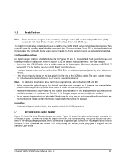
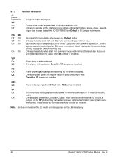
... mV pp from 8 KHz to 20 KHz. 250 mV pp from DC to 10 MHz. See Section 8.1 for maximum current requirements. Cheetah 15K.5 SCSI Product Manual, Rev. The drive protects against inadvertent writing during power-up . 5. To automatically delay motor start , are typical. See Table 3 for pin selection information....proper termination of frequencies covering a band from 20 KHz to each device. 4. Parameters, other than spindle start based on the target ID (SCSI ID) enable the Delay Motor Start option and disable the Enable Motor Start option on the J6 connector on LW models or on the ...
... mV pp from 8 KHz to 20 KHz. 250 mV pp from DC to 10 MHz. See Section 8.1 for maximum current requirements. Cheetah 15K.5 SCSI Product Manual, Rev. The drive protects against inadvertent writing during power-up . 5. To automatically delay motor start , are typical. See Table 3 for pin selection information....proper termination of frequencies covering a band from 20 KHz to each device. 4. Parameters, other than spindle start based on the target ID (SCSI ID) enable the Delay Motor Start option and disable the Enable Motor Start option on the J6 connector on LW models or on the ...
Cheetah 15K.5 SCSI Product Manual
Page 47
...is the only device on the bus. • If the drive is Molex 52747-0211 (Seagate part number 77679052). Refer to the end of the SCSI bus cable. Most host adapters use SCSI ID 7 because ID 7 is the highest priority on the bus set -up ...drive and do when installing a drive is usually done by installing small shorting jumpers on the connectors. Figure 11 shows the option select jumper connector for desired operation prior to Figures 10 and 11. A bag with 512 byte sectors. 8.1 Drive ID/option select header Figure 10 shows the drive ID select jumper connector. Cheetah 15K.5 SCSI...
...is the only device on the bus. • If the drive is Molex 52747-0211 (Seagate part number 77679052). Refer to the end of the SCSI bus cable. Most host adapters use SCSI ID 7 because ID 7 is the highest priority on the bus set -up ...drive and do when installing a drive is usually done by installing small shorting jumpers on the connectors. Figure 11 shows the option select jumper connector for desired operation prior to Figures 10 and 11. A bag with 512 byte sectors. 8.1 Drive ID/option select header Figure 10 shows the drive ID select jumper connector. Cheetah 15K.5 SCSI...

Cheetah 15K.5 SCSI Product Manual
Page 48
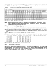
... SCSI ID = 3 SCSI ID = 4 SCSI ID = 5 SCSI ID = 6 SCSI ID = 7 SCSI ID = 8 SCSI ID = 9 For ID selection use jumpers as shown below. SCSI ID = 10 SCSI ID = 11 SCSI ID = 12 SCSI ID = 13 SCSI ID = 14 SCSI ID = 15 Reserved A3 A2 A1A0 Host Alternate N.C. J5 jumper header (on LW models only) 42 Cheetah 15K.5 SCSI Product Manual, Rev. Usage Plug 11 9 7 5 3 1 [4] A0 A1 A2 A3 +5V 12 10 8 6 4 2 +5V N.C. Pins 1, 3, 5, and 7 are normally not grounded. H Ground Drive Activity...
... SCSI ID = 3 SCSI ID = 4 SCSI ID = 5 SCSI ID = 6 SCSI ID = 7 SCSI ID = 8 SCSI ID = 9 For ID selection use jumpers as shown below. SCSI ID = 10 SCSI ID = 11 SCSI ID = 12 SCSI ID = 13 SCSI ID = 14 SCSI ID = 15 Reserved A3 A2 A1A0 Host Alternate N.C. J5 jumper header (on LW models only) 42 Cheetah 15K.5 SCSI Product Manual, Rev. Usage Plug 11 9 7 5 3 1 [4] A0 A1 A2 A3 +5V 12 10 8 6 4 2 +5V N.C. Pins 1, 3, 5, and 7 are normally not grounded. H Ground Drive Activity...
Cheetah 15K.5 SCSI Product Manual
Page 50
... terminator circuits on the LW model only. 44 Cheetah 15K.5 SCSI Product Manual, Rev. Default setting. Delayed start until Start Unit command received from host. PD On Parity checking and parity error reporting by SCSI ID times 12 seconds after power is supported on the drive. Drive can operate on the interface in low voltage differential...
... terminator circuits on the LW model only. 44 Cheetah 15K.5 SCSI Product Manual, Rev. Default setting. Delayed start until Start Unit command received from host. PD On Parity checking and parity error reporting by SCSI ID times 12 seconds after power is supported on the drive. Drive can operate on the interface in low voltage differential...
Cheetah 15K.5 SCSI Product Manual
Page 58
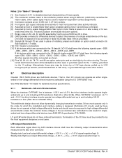
... with some host bus adapters. Table 9: Cheetah 15K.5 SCSI family drive Standard Inquiry data Bytes Data (HEX) 0-...73 20 72 65 73 65 72 76 65 64 20 [ ]1 03 means SCSI-3 (Ultra160) implemented. This setting will not affect the Ultra320 functionality of the drive. [ ]2 The drive...drive's firmware code was built. 9.3.1 Inquiry Vital Product data Instead of drive. Seagate has chosen to set this bit to 03, SCSI-3 (Ultra160) implemented, rather than 04, SCSI...ST373455LC 33 37 33 34 35 35 4C 43 20 [ ]4 Copyright Year - H Table 9 lists the Standard Inquiry command data that the drive...
... with some host bus adapters. Table 9: Cheetah 15K.5 SCSI family drive Standard Inquiry data Bytes Data (HEX) 0-...73 20 72 65 73 65 72 76 65 64 20 [ ]1 03 means SCSI-3 (Ultra160) implemented. This setting will not affect the Ultra320 functionality of the drive. [ ]2 The drive...drive's firmware code was built. 9.3.1 Inquiry Vital Product data Instead of drive. Seagate has chosen to set this bit to 03, SCSI-3 (Ultra160) implemented, rather than 04, SCSI...ST373455LC 33 37 33 34 35 35 4C 43 20 [ ]4 Copyright Year - H Table 9 lists the Standard Inquiry command data that the drive...

Cheetah 15K.5 SCSI Product Manual
Page 69
... [4] SCSI ID 7 [5] Pin 1 (check your adapter for LW drives Cheetah 15K.5 SCSI Product Manual, Rev. If end device, use external terminator and closed-end type 68-pin connector. SCSI daisy-chain interface cabling for Pin 1 location) [1] SCSI ID 1 Host Adapter PCB [3] SCSI ID 0 [2] [1] Closed end type 68-pin connector used . Recommended mating 80-position PCBA mount connectors: Straight-in connector Seagate...
... [4] SCSI ID 7 [5] Pin 1 (check your adapter for LW drives Cheetah 15K.5 SCSI Product Manual, Rev. If end device, use external terminator and closed-end type 68-pin connector. SCSI daisy-chain interface cabling for Pin 1 location) [1] SCSI ID 1 Host Adapter PCB [3] SCSI ID 0 [2] [1] Closed end type 68-pin connector used . Recommended mating 80-position PCBA mount connectors: Straight-in connector Seagate...

Cheetah 15K.5 SCSI Product Manual
Page 74
...-DB6 -DB5 -DB4 -DB3 -DB2 -DB1 -DB0 -DP1 -DB15 -DB14 -DB13 -DB12 +5 V +5 V +5 V NC [10] RMT-START [5] [9] [12] SCSI ID (0) [7] [9] [12] SCSI ID (2) [7] [9] [12] Connector contact number [3] 1 2 3 4 5 6 7 8 9 10 11 12 13 14 15 16 17 18 19 20 21 22 23 24... 53 54 55 56 57 58 59 60 61 62 63 64 65 66 67 68 69 70 71 72 73 74 75 76 77 78 79 80 Contact name[1] 12 V GND 12 V GND 12 V GND MATED 1...MATED 2 5 V GND 5 V GND ACTIVE LED OUT [4] [9] DLYD-START [6] [9] [12] SCSI ID (1) [7] [9] [12] SCSI ID (3) [7] [9] [12] Notes [ ]: See page following Table 20. 68 Cheetah 15K.5 SCSI Product Manual, Rev. H
...-DB6 -DB5 -DB4 -DB3 -DB2 -DB1 -DB0 -DP1 -DB15 -DB14 -DB13 -DB12 +5 V +5 V +5 V NC [10] RMT-START [5] [9] [12] SCSI ID (0) [7] [9] [12] SCSI ID (2) [7] [9] [12] Connector contact number [3] 1 2 3 4 5 6 7 8 9 10 11 12 13 14 15 16 17 18 19 20 21 22 23 24... 53 54 55 56 57 58 59 60 61 62 63 64 65 66 67 68 69 70 71 72 73 74 75 76 77 78 79 80 Contact name[1] 12 V GND 12 V GND 12 V GND MATED 1...MATED 2 5 V GND 5 V GND ACTIVE LED OUT [4] [9] DLYD-START [6] [9] [12] SCSI ID (1) [7] [9] [12] SCSI ID (3) [7] [9] [12] Notes [ ]: See page following Table 20. 68 Cheetah 15K.5 SCSI Product Manual, Rev. H

Cheetah 15K.5 SCSI Product Manual
Page 75
...-MSG -RST -ACK -BSY -ATN -DBP -DB7 -DB6 -DB5 -DB4 -DB3 -DB2 -DB1 -DB0 -DBP1 -DB15 -DB14 -DB13 -DB12 +5 V +5 V +5 V CHARGE NC [10] RMT_START [5] [9] [12] SCSI ID (0) [7] [9] [12] SCSI ID (2) [7] [9] [12] Connector contact number [3] 1 2 3 4 5 6 7 8 9 10 11 12 13 14 15 16 17 18 19 20 21 22 23 24 25 26 27 28 29 30... 63 64 65 66 67 68 69 70 71 72 73 74 75 76 77 78 79 80 Contact name[1] 12 V GND 12 V GND 12 V GND MATED 1 [12] NC [10] DIFFSNS [8] +DB11 +DB10 +DB9 +DB8 +I /O connector pin assignments [11] Note. Cheetah 15K.5 SCSI Product Manual, Rev. A minus sign preceding a signal name indicates ...
...-MSG -RST -ACK -BSY -ATN -DBP -DB7 -DB6 -DB5 -DB4 -DB3 -DB2 -DB1 -DB0 -DBP1 -DB15 -DB14 -DB13 -DB12 +5 V +5 V +5 V CHARGE NC [10] RMT_START [5] [9] [12] SCSI ID (0) [7] [9] [12] SCSI ID (2) [7] [9] [12] Connector contact number [3] 1 2 3 4 5 6 7 8 9 10 11 12 13 14 15 16 17 18 19 20 21 22 23 24 25 26 27 28 29 30... 63 64 65 66 67 68 69 70 71 72 73 74 75 76 77 78 79 80 Contact name[1] 12 V GND 12 V GND 12 V GND MATED 1 [12] NC [10] DIFFSNS [8] +DB11 +DB10 +DB9 +DB8 +I /O connector pin assignments [11] Note. Cheetah 15K.5 SCSI Product Manual, Rev. A minus sign preceding a signal name indicates ...
Cheetah 15K.5 SCSI Product Manual
Page 76
...and including 160 M transfers/s or less (Fast-160 or Ultra320 SCSI). All other means. 9.7 Electrical description Cheetah 15K.5 SCSI drives are controlled to and including 20 M transfers/s (Fast-20 or Ultra SCSI). See ANSI Standard T10/1320D for detailed electrical specifications. 9.7.1 ...users. That is grounded. [9] Signals [4] through a pull-up SCSI bus ID in place of 12 sec- Other cables types may be used in drive. [8] GND provides a means for host front panel hard drive activity indicator. [5] Asserted by host to implement equivalent contact assignments....
...and including 160 M transfers/s or less (Fast-160 or Ultra320 SCSI). All other means. 9.7 Electrical description Cheetah 15K.5 SCSI drives are controlled to and including 20 M transfers/s (Fast-20 or Ultra SCSI). See ANSI Standard T10/1320D for detailed electrical specifications. 9.7.1 ...users. That is grounded. [9] Signals [4] through a pull-up SCSI bus ID in place of 12 sec- Other cables types may be used in drive. [8] GND provides a means for host front panel hard drive activity indicator. [5] Asserted by host to implement equivalent contact assignments....

Cheetah 15K.5 SCSI Product Manual
Page 88
... 15, 16 product data page 52 programmable drive capacity 10 R radio interference regulations 3 RCD...SCSI bus cable 41 SCSI bus condition 57 SCSI bus ID 70 SCSI bus phase sequence 57 SCSI command 37 SCSI Commands Reference Manual 5 SCSI I/O connector 60 82 SCSI ID 41, 44 SCSI interface 13, 60 SCSI interface cable 61 SCSI interface commands supported 48 SCSI interface connector 58 SCSI interface data 12 SCSI Interface Product Manual 3, 5, 7 SCSI systems error 39 SCSI systems error management 39 Seagate...73 terminator requirements 41, 73 thermal monitor 19 Cheetah 15K.5 SCSI Product Manual, Rev.
... 15, 16 product data page 52 programmable drive capacity 10 R radio interference regulations 3 RCD...SCSI bus cable 41 SCSI bus condition 57 SCSI bus ID 70 SCSI bus phase sequence 57 SCSI command 37 SCSI Commands Reference Manual 5 SCSI I/O connector 60 82 SCSI ID 41, 44 SCSI interface 13, 60 SCSI interface cable 61 SCSI interface commands supported 48 SCSI interface connector 58 SCSI interface data 12 SCSI Interface Product Manual 3, 5, 7 SCSI systems error 39 SCSI systems error management 39 Seagate...73 terminator requirements 41, 73 thermal monitor 19 Cheetah 15K.5 SCSI Product Manual, Rev.
Installation Guide
Page 21
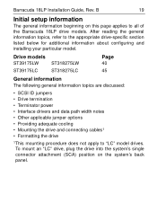
...'s single connector attachment (SCA) position on this page applies to all of the Barracuda 18LP drive models. Drive models ST39175LW ST39175LC ST318275LW ST318275LC Page 40 45 General information The following general information topics are discussed: • SCSI ID jumpers • Drive termination • Terminator power • Interface drivers and data path width notes • Other...
...'s single connector attachment (SCA) position on this page applies to all of the Barracuda 18LP drive models. Drive models ST39175LW ST39175LC ST318275LW ST318275LC Page 40 45 General information The following general information topics are discussed: • SCSI ID jumpers • Drive termination • Terminator power • Interface drivers and data path width notes • Other...
Installation Guide
Page 22
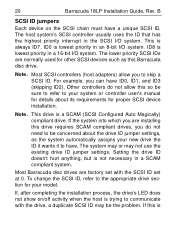
... controllers do not need to be concerned about its requirements for proper SCSI device installation. Most Barracuda disc drives are installing this Barracuda disc drive. The lower priority SCSI IDs are normally used for details about the drive ID jumper settings, as this drive requires SCAM compliant drives, you can have ID0, ID1, and ID3 (skipping ID2). For example...
... controllers do not need to be concerned about its requirements for proper SCSI device installation. Most Barracuda disc drives are installing this Barracuda disc drive. The lower priority SCSI IDs are normally used for details about the drive ID jumper settings, as this drive requires SCAM compliant drives, you can have ID0, ID1, and ID3 (skipping ID2). For example...

Installation Guide
Page 23
...refer to your system or controller documentation to see how this means the SCSI controller is any disc drive, scanner, tape backup unit, or other SCSI devices installed, terminate only the end devices on the SCSI chain has its SCSI ID numbering recommendations. Note. Barracuda 18LP Installation Guide, Rev. This means you...remain terminated even if they are terminated). A SCSI "device" is no longer on both are in Figure 2 shows an internal hard disc at one end of the chain. The top example in the middle of the SCSI bus with the SCSI controller at the other end (both logical ...
...refer to your system or controller documentation to see how this means the SCSI controller is any disc drive, scanner, tape backup unit, or other SCSI devices installed, terminate only the end devices on the SCSI chain has its SCSI ID numbering recommendations. Note. Barracuda 18LP Installation Guide, Rev. This means you...remain terminated even if they are terminated). A SCSI "device" is no longer on both are in Figure 2 shows an internal hard disc at one end of the chain. The top example in the middle of the SCSI bus with the SCSI controller at the other end (both logical ...

Installation Guide
Page 29
...adapter B 27 "LW" Model Drive Note. Multiple-drive "LW" model connection to ID8 (ID 8 very lowest). [6] Last drive on the end of devices allowed. [5] SCSI ID7 has highest arbitration priority.... Barracuda 18LP Installation Guide, Rev. The cable length restriction limits the total number of the daisy chain. No terminator. [3] Host need not be on the daisy chain. [6] Terminator [1] 2 through X SCSI devices [4] SCSI ID 1 Pin 1 (check your adapter for Pin 1 location) [2] SCSI ID 0 SCSI ID...
...adapter B 27 "LW" Model Drive Note. Multiple-drive "LW" model connection to ID8 (ID 8 very lowest). [6] Last drive on the end of devices allowed. [5] SCSI ID7 has highest arbitration priority.... Barracuda 18LP Installation Guide, Rev. The cable length restriction limits the total number of the daisy chain. No terminator. [3] Host need not be on the daisy chain. [6] Terminator [1] 2 through X SCSI devices [4] SCSI ID 1 Pin 1 (check your adapter for Pin 1 location) [2] SCSI ID 0 SCSI ID...

Installation Guide
Page 42
Terminating the drive "LW" model drives do not have internal terminators or any other way of adding internal termination to set the SCSI ID (see Figure 8). B Setting the SCSI ID jumpers Use the J6 jumper block to the drive. External termination for these drives must be supplied by the host equipment. Optional connections to switching circuits in the illustration. 40 LW drives Barracuda 18LP Installation Guide, Rev. To change the SCSI ID, install jumpers on the appropriate pins as shown in host equipment are provided on J1 auxiliary to set the SCSI ID (Figure 7).
Terminating the drive "LW" model drives do not have internal terminators or any other way of adding internal termination to set the SCSI ID (see Figure 8). B Setting the SCSI ID jumpers Use the J6 jumper block to the drive. External termination for these drives must be supplied by the host equipment. Optional connections to switching circuits in the illustration. 40 LW drives Barracuda 18LP Installation Guide, Rev. To change the SCSI ID, install jumpers on the appropriate pins as shown in host equipment are provided on J1 auxiliary to set the SCSI ID (Figure 7).

Installation Guide
Page 43
B 41 LW drives Drive Front Jumper Plug (enlarged to show detail) J6 [1] Pin 1 Figure 7. Reserved LR E D E S A3 A2 A1A0 SCSI ID = 0 (default) SCSI ID = 1 SCSI ID = 2 SCSI ID = 3 SCSI ID = 4 SCSI ID = 5 SCSI ID = 6 SCSI ID = 7 SCSI ID = 8 SCSI ID = 9 SCSI ID = 10 SCSI ID = 11 SCSI ID = 12 SCSI ID = 13 SCSI ID = 14 SCSI ID = 15 Setting the SCSI ID on model LW drives Barracuda 18LP Installation Guide, Rev.
B 41 LW drives Drive Front Jumper Plug (enlarged to show detail) J6 [1] Pin 1 Figure 7. Reserved LR E D E S A3 A2 A1A0 SCSI ID = 0 (default) SCSI ID = 1 SCSI ID = 2 SCSI ID = 3 SCSI ID = 4 SCSI ID = 5 SCSI ID = 6 SCSI ID = 7 SCSI ID = 8 SCSI ID = 9 SCSI ID = 10 SCSI ID = 11 SCSI ID = 12 SCSI ID = 13 SCSI ID = 14 SCSI ID = 15 Setting the SCSI ID on model LW drives Barracuda 18LP Installation Guide, Rev.

Installation Guide
Page 44
... connector for remote switching as shown below. B 68 Pin SCSI I/O +5V Connector Pin 1 Ground J5 Pin 1 J1-DC Power Drive HDA Rear J1 SCSI ID = 0 SCSI ID = 1 SCSI ID = 2 4P (default) 3P2P 1P PCB SCSI ID = 3 SCSI ID = 4 SCSI ID = 5 SCSI ID = 6 SCSI ID = 7 SCSI ID = 8 SCSI ID = 9 SCSI ID = 10 For ID selection use jumpers as shown or connect a cable for model "LW" drive alternate ID select and LED connection of an external Activity LED. Figure...
... connector for remote switching as shown below. B 68 Pin SCSI I/O +5V Connector Pin 1 Ground J5 Pin 1 J1-DC Power Drive HDA Rear J1 SCSI ID = 0 SCSI ID = 1 SCSI ID = 2 4P (default) 3P2P 1P PCB SCSI ID = 3 SCSI ID = 4 SCSI ID = 5 SCSI ID = 6 SCSI ID = 7 SCSI ID = 8 SCSI ID = 9 SCSI ID = 10 For ID selection use jumpers as shown or connect a cable for model "LW" drive alternate ID select and LED connection of an external Activity LED. Figure...

Installation Guide
Page 45
... Motor Start jumper is not connected) Disable the Delay Motor Start option. Motor start (default). For example, if the SCSI ID = 2, the drive starts in Figures 9 and 10. Parity Check option Enable parity check of SCSI bus. B 43 LW drives Other applicable jumper options Other option jumpers are available as illustrated in 24 seconds. CATH...
... Motor Start jumper is not connected) Disable the Delay Motor Start option. Motor start (default). For example, if the SCSI ID = 2, the drive starts in Figures 9 and 10. Parity Check option Enable parity check of SCSI bus. B 43 LW drives Other applicable jumper options Other option jumpers are available as illustrated in 24 seconds. CATH...

Installation Guide
Page 47
Terminating the drive "LC" model drives do not have internal terminators or any other way of adding internal termination to select SCSI ID. External termination for "LC" model drives is normally set over the SCSI bus by the host equipment. Users need not install jumpers to the drive. Barracuda 18LP Installation Guide, Rev. B 45 LC drives Setting the SCSIWIDC/jDumC pderirvses section The SCSI ID for these drives must be supplied by the host system using connector contacts 39 (ID0), 40 (ID2), 79 (ID1), and 80 (ID3).
Terminating the drive "LC" model drives do not have internal terminators or any other way of adding internal termination to select SCSI ID. External termination for "LC" model drives is normally set over the SCSI bus by the host equipment. Users need not install jumpers to the drive. Barracuda 18LP Installation Guide, Rev. B 45 LC drives Setting the SCSIWIDC/jDumC pderirvses section The SCSI ID for these drives must be supplied by the host system using connector contacts 39 (ID0), 40 (ID2), 79 (ID1), and 80 (ID3).

