Cheetah 15K.5 SCSI Product Manual
Page 5
...Figure 17. Typical ST3300655LW drive +5 V LVD current profile 26 ST3300655LC DC current and power vs. IOPS (LVD 29 Locations of Figures Figure 1. IOPS (LVD 28 ST373455LC DC current and power...jumper header (on LW models only 42 J6 option select header (on LW models only 43 Air flow (suggested 45 LW model drive physical interface (68-pin J1 SCSI I/O connector 59 LC model drive...drives 63 Nonshielded 68-pin SCSI device connector used on LW drives 64 Nonshielded 80-pin SCSI SCA-2 connector used on LC drives 65 Typical SE-LVD alternative transmitter receiver circuits 71 Cheetah...
...Figure 17. Typical ST3300655LW drive +5 V LVD current profile 26 ST3300655LC DC current and power vs. IOPS (LVD 29 Locations of Figures Figure 1. IOPS (LVD 28 ST373455LC DC current and power...jumper header (on LW models only 42 J6 option select header (on LW models only 43 Air flow (suggested 45 LW model drive physical interface (68-pin J1 SCSI I/O connector 59 LC model drive...drives 63 Nonshielded 68-pin SCSI device connector used on LW drives 64 Nonshielded 80-pin SCSI SCA-2 connector used on LC drives 65 Typical SE-LVD alternative transmitter receiver circuits 71 Cheetah...

Cheetah 15K.5 SCSI Product Manual
Page 16
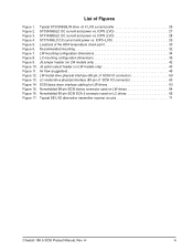
...list block descriptor number of jumper plugs used for the J5 and J6 option select jumper headers (on sparing scheme and sector size requested. • Single unit shipping pack. H 3.5.1 Programmable drive capacity Using the Mode Select command, the drive can be ordered. 3.8...Agency Specifications, part number 75789512, usually ships with the Cheetah 15K.5 Installation Guide, part number 100384777, and the Safety and Regulatory Agency Specifications, part number 75789512 (unless otherwise specified). The drive is currently formatted to provide maximum protection against transit ...
...list block descriptor number of jumper plugs used for the J5 and J6 option select jumper headers (on sparing scheme and sector size requested. • Single unit shipping pack. H 3.5.1 Programmable drive capacity Using the Mode Select command, the drive can be ordered. 3.8...Agency Specifications, part number 75789512, usually ships with the Cheetah 15K.5 Installation Guide, part number 100384777, and the Safety and Regulatory Agency Specifications, part number 75789512 (unless otherwise specified). The drive is currently formatted to provide maximum protection against transit ...
Cheetah 15K.5 SCSI Product Manual
Page 47
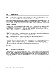
... information required when servicing the product. If necessary see Figure 10), or via the drive to host I/O signals on . Figure 11 shows the option select jumper connector for Seagate support services telephone numbers. • Do not remove the manufacturer's installed labels from... the factory low level formatted with additional labels, as the host adapter. The notes following the figures describe the functions of the drive is to Figures 10 and 11. Cheetah...
... information required when servicing the product. If necessary see Figure 10), or via the drive to host I/O signals on . Figure 11 shows the option select jumper connector for Seagate support services telephone numbers. • Do not remove the manufacturer's installed labels from... the factory low level formatted with additional labels, as the host adapter. The notes following the figures describe the functions of the drive is to Figures 10 and 11. Cheetah...

Cheetah 15K.5 SCSI Product Manual
Page 48
... a cable for 250 ms after a Reset or PWR ON to allow drive to establish drive ID. Pins 1, 3, 5, and 7 are optional connections to switching circuits in host equipment to read SCSI ID selected. H Figure 10. J5 jumper header (on LW models only) 42 Cheetah 15K.5 SCSI Product Manual, Rev. They are normally not grounded. Usage...
... a cable for 250 ms after a Reset or PWR ON to allow drive to establish drive ID. Pins 1, 3, 5, and 7 are optional connections to switching circuits in host equipment to read SCSI ID selected. H Figure 10. J5 jumper header (on LW models only) 42 Cheetah 15K.5 SCSI Product Manual, Rev. They are normally not grounded. Usage...
Cheetah 15K.5 SCSI Product Manual
Page 49
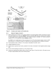
...and 11. [1] Notes explaining the functions of the various jumpers on 80-pin J1 I/O connector. See tables 19 and 20, note 9. [3] Voltage supplied by the drive. [4] Dashed area is factory default condition. Drive Front Jumper Plug (enlarged to SCSI Bus Parity Disable Delay Motor ...These signals are configured with a jumper on LC models does not have connector J5 or J6. H 43 Power to show detail) Reserved J6 [1] [5] Pin 1 T P D MWS P DSEPE Term. The PCBA on those positions when shipped from factory. "On" means a jumper is installed; Cheetah 15K.5 SCSI Product Manual, ...
...and 11. [1] Notes explaining the functions of the various jumpers on 80-pin J1 I/O connector. See tables 19 and 20, note 9. [3] Voltage supplied by the drive. [4] Dashed area is factory default condition. Drive Front Jumper Plug (enlarged to SCSI Bus Parity Disable Delay Motor ...These signals are configured with a jumper on LC models does not have connector J5 or J6. H 43 Power to show detail) Reserved J6 [1] [5] Pin 1 T P D MWS P DSEPE Term. The PCBA on those positions when shipped from factory. "On" means a jumper is installed; Cheetah 15K.5 SCSI Product Manual, ...
Cheetah 15K.5 SCSI Product Manual
Page 50
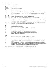
... terminator circuits on the LW model only. 44 Cheetah 15K.5 SCSI Product Manual, Rev. TP Off The drive does not supply terminator power to external terminators or to use single-ended I/O drivers/receivers only. 8.1.2 Function description J6 jumper installation SE On Off Jumper function description Forces drive to the SCSI bus I/O cable. Default is applied...
... terminator circuits on the LW model only. 44 Cheetah 15K.5 SCSI Product Manual, Rev. TP Off The drive does not supply terminator power to external terminators or to use single-ended I/O drivers/receivers only. 8.1.2 Function description J6 jumper installation SE On Off Jumper function description Forces drive to the SCSI bus I/O cable. Default is applied...
Cheetah 15K.5 SCSI Product Manual
Page 54
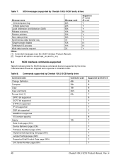
... N N N N Y N Y Y Y Y Y N Y Y Y Y Y Y Y Y 48 Cheetah 15K.5 SCSI Product Manual, Rev. OEM standard drives are supported by the drive. Table 8: Commands supported by Cheetah 15K.5 SCSI family drive Command name Change Definition Compare Copy Copy and Verify Format Unit [1] DPRY bit supported DCRT bit supported STPF bit supported ... Implemented Operating Def page (81h) Jumper Settings page (C2h) Supported Vital Product Data page (00h) Unit Serial Number page (80h) Command code 40h 39h 18h 3Ah 04h 12h Supported by Cheetah 15K.5 SCSI family drives Message name Message code Ordered queue tag...
... N N N N Y N Y Y Y Y Y N Y Y Y Y Y Y Y Y 48 Cheetah 15K.5 SCSI Product Manual, Rev. OEM standard drives are supported by the drive. Table 8: Commands supported by Cheetah 15K.5 SCSI family drive Command name Change Definition Compare Copy Copy and Verify Format Unit [1] DPRY bit supported DCRT bit supported STPF bit supported ... Implemented Operating Def page (81h) Jumper Settings page (C2h) Supported Vital Product Data page (00h) Unit Serial Number page (80h) Command code 40h 39h 18h 3Ah 04h 12h Supported by Cheetah 15K.5 SCSI family drives Message name Message code Ordered queue tag...
Cheetah 15K.5 SCSI Product Manual
Page 66
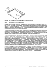
... or PCBA circuit runs that can operate either SE or LVD. A single drive connected via a cable to reject newer Ultra320 protocol extensions that can be enabled by the end user or designers of a jumper plug (TE) on SE and LVD buses. 80-pin SCSI I /O... impedance in an acceptable manner (per applicable SCSI Standards) to a host 80-pin I /O connector) 9.6.2 SCSI interface physical description Cheetah 15K.5 SCSI drives support the physical interface requirements of the Ultra320 SCSI Parallel Interface-4 (SPI-4), and operate compatibly at various interface transfer rates on the device...
... or PCBA circuit runs that can operate either SE or LVD. A single drive connected via a cable to reject newer Ultra320 protocol extensions that can be enabled by the end user or designers of a jumper plug (TE) on SE and LVD buses. 80-pin SCSI I /O... impedance in an acceptable manner (per applicable SCSI Standards) to a host 80-pin I /O connector) 9.6.2 SCSI interface physical description Cheetah 15K.5 SCSI drives support the physical interface requirements of the Ultra320 SCSI Parallel Interface-4 (SPI-4), and operate compatibly at various interface transfer rates on the device...
Cheetah 15K.5 SCSI Product Manual
Page 76
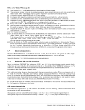
...DB11, -DB12, -DB13, -DB14, -DB15, and -DBP1. onds times drive ID). All other means. 9.7 Electrical description Cheetah 15K.5 SCSI drives are multimode devices. The preferred electrical connection at Ultra2 or faster SCSI data rates... to the 16 data bit LVD I /O lines must operate only in place of installing jumpers and cables on 0.050 inch (1.27 mm) centers. [4] Front panel LED signal; This... (open for the '1' setting, grounded for the '0' setting). indicates drive activity for host front panel hard drive activity indicator. [5] Asserted by host to enable Motor Start option (enables...
...DB11, -DB12, -DB13, -DB14, -DB15, and -DBP1. onds times drive ID). All other means. 9.7 Electrical description Cheetah 15K.5 SCSI drives are multimode devices. The preferred electrical connection at Ultra2 or faster SCSI data rates... to the 16 data bit LVD I /O lines must operate only in place of installing jumpers and cables on 0.050 inch (1.27 mm) centers. [4] Front panel LED signal; This... (open for the '1' setting, grounded for the '0' setting). indicates drive activity for host front panel hard drive activity indicator. [5] Asserted by host to enable Motor Start option (enables...

Cheetah 15K.5 SCSI Product Manual
Page 79
.... Cheetah 15K.5 SCSI Product Manual, Rev. See Section 8.1 for illustrations that plug between the SCSI I/O cable and the drive I/O connector or on the end of a short I /O connector are designed to be plugged into a backpanel connector without cabling. 9.9 Terminator power LW drives You can be purchased that show how to place jumpers for this configuration. H 73...
.... Cheetah 15K.5 SCSI Product Manual, Rev. See Section 8.1 for illustrations that plug between the SCSI I/O cable and the drive I/O connector or on the end of a short I /O connector are designed to be plugged into a backpanel connector without cabling. 9.9 Terminator power LW drives You can be purchased that show how to place jumpers for this configuration. H 73...
Cheetah 15K.5 SCSI Product Manual
Page 86
...drive 33 drive activity 70 drive activity LED 76 drive capacity 11 programmable 10 drive default mode parameter 41 drive firmware 53 drive ID 41 drive ID select jumper connector 41 drive ID/option select header 41 drive interface connector 62 drive internal defects and errors 37 drive mounting 34, 46 constraints 15 drive orientation 45 drive power 41 drive...41 front panel 34 front panel LED 70 G gradient 30 ground return 24 grounding 46 H hard reset 53 HDA 7, 46 heat removal 45 host 44, 51, 60, 63 host adapter 41...interface data 12 interface requirements 47 Cheetah 15K.5 SCSI Product Manual, Rev.
...drive 33 drive activity 70 drive activity LED 76 drive capacity 11 programmable 10 drive default mode parameter 41 drive firmware 53 drive ID 41 drive ID select jumper connector 41 drive ID/option select header 41 drive interface connector 62 drive internal defects and errors 37 drive mounting 34, 46 constraints 15 drive orientation 45 drive power 41 drive...41 front panel 34 front panel LED 70 G gradient 30 ground return 24 grounding 46 H hard reset 53 HDA 7, 46 heat removal 45 host 44, 51, 60, 63 host adapter 41...interface data 12 interface requirements 47 Cheetah 15K.5 SCSI Product Manual, Rev.

Cheetah 15K.5 SCSI Product Manual
Page 87
...62 mating flat cable connector 62 maximum current requirements 25 maximum operating current 24 maximum starting current 23, 24 ME jumper 44 mean time between failure (MTBF) 16 media 8, 53 Media Pre-Scan 39 message protocol 58 message protocol ...44 parity error 44 PCB 43 PCBA 41, 46, 53, 59, 60, 63 PCBA circuit run 60 PD jumper 44 peak bits/inch 11 peak starting current 24 performance characteristics 11 performance degradation 31 peripheral I/O cable 25 physical ...25 power control switch 13 power dissipation 27 power distribution 3 power sequencing 25 Cheetah 15K.5 SCSI Product Manual, Rev.
...62 mating flat cable connector 62 maximum current requirements 25 maximum operating current 24 maximum starting current 23, 24 ME jumper 44 mean time between failure (MTBF) 16 media 8, 53 Media Pre-Scan 39 message protocol 58 message protocol ...44 parity error 44 PCB 43 PCBA 41, 46, 53, 59, 60, 63 PCBA circuit run 60 PD jumper 44 peak bits/inch 11 peak starting current 24 performance characteristics 11 performance degradation 31 peripheral I/O cable 25 physical ...25 power control switch 13 power dissipation 27 power distribution 3 power sequencing 25 Cheetah 15K.5 SCSI Product Manual, Rev.

Cheetah 15K.5 SCSI Product Manual
Page 88
...regulation 3 See also cooling temperature sensor 19 termination 25 terminator enable jumper TE 63 terminator power 73 terminator requirements 41, 73 thermal monitor 19 Cheetah 15K.5 SCSI Product Manual, Rev. See S.M.A.R.T. power supply voltage... 13 prefetch segmented cache control 13 preventive maintenance 15, 16 product data page 52 programmable drive capacity 10 R radio interference regulations 3 RCD bit 13 read error rate 15 read error... error 39 SCSI systems error management 39 Seagate support service 41 sector sizes 12 seek error 15 defined 16 Self-Monitoring Analysis and Reporting ...
...regulation 3 See also cooling temperature sensor 19 termination 25 terminator enable jumper TE 63 terminator power 73 terminator requirements 41, 73 thermal monitor 19 Cheetah 15K.5 SCSI Product Manual, Rev. See S.M.A.R.T. power supply voltage... 13 prefetch segmented cache control 13 preventive maintenance 15, 16 product data page 52 programmable drive capacity 10 R radio interference regulations 3 RCD bit 13 read error rate 15 read error... error 39 SCSI systems error management 39 Seagate support service 41 sector sizes 12 seek error 15 defined 16 Self-Monitoring Analysis and Reporting ...

Cheetah 15K.5 SCSI Product Manual
Page 89
H 83 TP1 position 44 tracks/inch 11 tracks/surface, total 11 transfer period 58 transmitter receiver circuits 71 Tunneling Magnetoresistive heads 7 U Ultra160 53 Ultra160 mode 48 Ultra160 SCSI interface 7 Ultra320 SCSI controller 8 unformatted 9 Unrecoverable Errors 15 V vibration 31, 33 vital product data 52 volatile memory 53 voltage 23, 24 W warranty 9, 21 wet bulb temperature 30 wide Ultra160 SCSI interface 7 WP jumper 44 write protect 44 write retry count 37 Z zoned bit recording (ZBR) 8 Cheetah 15K.5 SCSI Product Manual, Rev.
H 83 TP1 position 44 tracks/inch 11 tracks/surface, total 11 transfer period 58 transmitter receiver circuits 71 Tunneling Magnetoresistive heads 7 U Ultra160 53 Ultra160 mode 48 Ultra160 SCSI interface 7 Ultra320 SCSI controller 8 unformatted 9 Unrecoverable Errors 15 V vibration 31, 33 vital product data 52 volatile memory 53 voltage 23, 24 W warranty 9, 21 wet bulb temperature 30 wide Ultra160 SCSI interface 7 WP jumper 44 write protect 44 write retry count 37 Z zoned bit recording (ZBR) 8 Cheetah 15K.5 SCSI Product Manual, Rev.
Installation Guide
Page 21
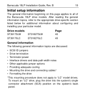
... information The general information beginning on the system's back panel. Barracuda 18LP Installation Guide, Rev. Drive models ST39175LW ST39175LC ST318275LW ST318275LC Page 40 45 General information The following general information topics are discussed: • SCSI ID jumpers • Drive termination • Terminator power • Interface drivers and data path width notes • Other...
... information The general information beginning on the system's back panel. Barracuda 18LP Installation Guide, Rev. Drive models ST39175LW ST39175LC ST318275LW ST318275LC Page 40 45 General information The following general information topics are discussed: • SCSI ID jumpers • Drive termination • Terminator power • Interface drivers and data path width notes • Other...
Installation Guide
Page 22
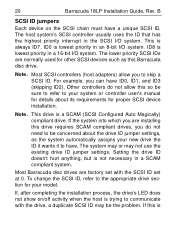
... show on the SCSI chain must have ID0, ID1, and ID3 (skipping ID2). If this Barracuda disc drive. The lower priority SCSI IDs are factory set at 0. B SCSI ID jumpers Each device on /off activity when the host is lowest priority in the SCSI I/O system. Note. The... may or may be concerned about its requirements for details about the drive ID jumper settings, as this is a SCAM (SCSI Configured Auto Magically) compliant drive. 20 Barracuda 18LP Installation Guide, Rev. Most Barracuda disc drives are normally used for other SCSI devices such as the system automatically assigns...
... show on the SCSI chain must have ID0, ID1, and ID3 (skipping ID2). If this Barracuda disc drive. The lower priority SCSI IDs are factory set at 0. B SCSI ID jumpers Each device on /off activity when the host is lowest priority in the SCSI I/O system. Note. The... may or may be concerned about its requirements for details about the drive ID jumper settings, as this is a SCAM (SCSI Configured Auto Magically) compliant drive. 20 Barracuda 18LP Installation Guide, Rev. Most Barracuda disc drives are normally used for other SCSI devices such as the system automatically assigns...

Installation Guide
Page 25
... data transfer rates shown. The state of the bus receivers/drivers operate in single-ended mode. However, the SE jumper on a daisy-chain cable for I /O daisy chain with "LW" or "LC" model drives. If "DIFFSNS" is between .7V and 1.9V, all of the I/O "DIFFSNS" line determines whether the devices... lines must not be terminated the same as the used lines. Barracuda 18LP Installation Guide, Rev. The host device cannot override the SE jumper. Note. however, you can operate with that kind of devices allowed on J2 forces "DIFFSNS" to .6V), all bus receiver/drivers operate...
... data transfer rates shown. The state of the bus receivers/drivers operate in single-ended mode. However, the SE jumper on a daisy-chain cable for I /O daisy chain with "LW" or "LC" model drives. If "DIFFSNS" is between .7V and 1.9V, all of the I/O "DIFFSNS" line determines whether the devices... lines must not be terminated the same as the used lines. Barracuda 18LP Installation Guide, Rev. The host device cannot override the SE jumper. Note. however, you can operate with that kind of devices allowed on J2 forces "DIFFSNS" to .6V), all bus receiver/drivers operate...

Installation Guide
Page 42
External termination for these drives must be supplied by the host equipment. Terminating the drive "LW" model drives do not have internal terminators or any other way of adding internal termination to set the SCSI ID (see Figure 8). To change the SCSI ID, install jumpers on J1 auxiliary to switching circuits in host equipment are provided on the appropriate pins as shown in the illustration. Optional connections to set the SCSI ID (Figure 7). B Setting the SCSI ID jumpers Use the J6 jumper block to the drive. 40 LW drives Barracuda 18LP Installation Guide, Rev.
External termination for these drives must be supplied by the host equipment. Terminating the drive "LW" model drives do not have internal terminators or any other way of adding internal termination to set the SCSI ID (see Figure 8). To change the SCSI ID, install jumpers on J1 auxiliary to switching circuits in host equipment are provided on the appropriate pins as shown in the illustration. Optional connections to set the SCSI ID (Figure 7). B Setting the SCSI ID jumpers Use the J6 jumper block to the drive. 40 LW drives Barracuda 18LP Installation Guide, Rev.

Installation Guide
Page 43
Barracuda 18LP Installation Guide, Rev. Reserved LR E D E S A3 A2 A1A0 SCSI ID = 0 (default) SCSI ID = 1 SCSI ID = 2 SCSI ID = 3 SCSI ID = 4 SCSI ID = 5 SCSI ID = 6 SCSI ID = 7 SCSI ID = 8 SCSI ID = 9 SCSI ID = 10 SCSI ID = 11 SCSI ID = 12 SCSI ID = 13 SCSI ID = 14 SCSI ID = 15 Setting the SCSI ID on model LW drives B 41 LW drives Drive Front Jumper Plug (enlarged to show detail) J6 [1] Pin 1 Figure 7.
Barracuda 18LP Installation Guide, Rev. Reserved LR E D E S A3 A2 A1A0 SCSI ID = 0 (default) SCSI ID = 1 SCSI ID = 2 SCSI ID = 3 SCSI ID = 4 SCSI ID = 5 SCSI ID = 6 SCSI ID = 7 SCSI ID = 8 SCSI ID = 9 SCSI ID = 10 SCSI ID = 11 SCSI ID = 12 SCSI ID = 13 SCSI ID = 14 SCSI ID = 15 Setting the SCSI ID on model LW drives B 41 LW drives Drive Front Jumper Plug (enlarged to show detail) J6 [1] Pin 1 Figure 7.

Installation Guide
Page 44
... 1 Ground J5 Pin 1 J1-DC Power Drive HDA Rear J1 SCSI ID = 0 SCSI ID = 1 SCSI ID = 2 4P (default) 3P2P 1P PCB SCSI ID = 3 SCSI ID = 4 SCSI ID = 5 SCSI ID = 6 SCSI ID = 7 SCSI ID = 8 SCSI ID = 9 SCSI ID = 10 For ID selection use jumpers as shown or connect a cable for model ..."LW" drive alternate ID select and LED connection Using J5 connector for remote switching as shown below. not grounded. Remote Switches +5V 12...
... 1 Ground J5 Pin 1 J1-DC Power Drive HDA Rear J1 SCSI ID = 0 SCSI ID = 1 SCSI ID = 2 4P (default) 3P2P 1P PCB SCSI ID = 3 SCSI ID = 4 SCSI ID = 5 SCSI ID = 6 SCSI ID = 7 SCSI ID = 8 SCSI ID = 9 SCSI ID = 10 For ID selection use jumpers as shown or connect a cable for model ..."LW" drive alternate ID select and LED connection Using J5 connector for remote switching as shown below. not grounded. Remote Switches +5V 12...


