Cheetah 15K.5 SCSI Product Manual
Page 4
...-Reallocation 40 7.7 Idle Read After Write 40 8.0 Installation 41 8.1 Drive ID/option select header 41 8.1.1 Notes for Figures 10 and 11 43 8.1.2 Function description 44 8.2 Drive orientation 45 8.3 Cooling 45 8.4 Drive mounting 46 8.5 Grounding 46 9.0 Interface requirements 47 9.1 General description ... 9.7 Electrical description 70 9.7.1 Multimode-SE and LVD alternatives 70 9.8 Terminator requirements 73 9.9 Terminator power 73 9.10 Disc drive SCSI timing 74 9.11 Drive activity LED 76 10.0 Seagate Technology support services 77 ii Cheetah 15K.5 SCSI Product Manual, Rev.
...-Reallocation 40 7.7 Idle Read After Write 40 8.0 Installation 41 8.1 Drive ID/option select header 41 8.1.1 Notes for Figures 10 and 11 43 8.1.2 Function description 44 8.2 Drive orientation 45 8.3 Cooling 45 8.4 Drive mounting 46 8.5 Grounding 46 9.0 Interface requirements 47 9.1 General description ... 9.7 Electrical description 70 9.7.1 Multimode-SE and LVD alternatives 70 9.8 Terminator requirements 73 9.9 Terminator power 73 9.10 Disc drive SCSI timing 74 9.11 Drive activity LED 76 10.0 Seagate Technology support services 77 ii Cheetah 15K.5 SCSI Product Manual, Rev.

Cheetah 15K.5 SCSI Product Manual
Page 31
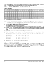
Daisy-chain operation requires that power be available to each device. 4. Cheetah 15K.5 SCSI Product Manual, Rev. Parameters, other than spindle start based on the target ID (SCSI ID) enable the Delay Motor Start option and disable the Enable Motor Start option on the J6 connector on ... to the SCSI bus terminator to ensure proper termination of frequencies covering a band from 20 KHz to 5 MHz. 6.2.2 Power sequencing The drive does not require power sequencing. See Table 3 for pin selection information. Maximum allowed noise values given below are typical. To delay the ...
Daisy-chain operation requires that power be available to each device. 4. Cheetah 15K.5 SCSI Product Manual, Rev. Parameters, other than spindle start based on the target ID (SCSI ID) enable the Delay Motor Start option and disable the Enable Motor Start option on the J6 connector on ... to the SCSI bus terminator to ensure proper termination of frequencies covering a band from 20 KHz to 5 MHz. 6.2.2 Power sequencing The drive does not require power sequencing. See Table 3 for pin selection information. Maximum allowed noise values given below are typical. To delay the ...
Cheetah 15K.5 SCSI Product Manual
Page 47
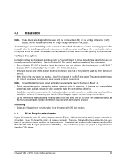
...and perform the set up using remote switches. Some users connect cables to set the drive SCSI ID and set -up certain operating options. Drive default mode parameters are needed for Seagate support services telephone numbers. • Do not remove the manufacturer's installed labels from the...If necessary see Figure 10), or via the drive to the end of the various jumper positions on the bus. • If the drive is shipped with 512 byte sectors. 8.1 Drive ID/option select header Figure 10 shows the drive ID select jumper connector. Cheetah 15K.5 SCSI Product Manual, Rev.
...and perform the set up using remote switches. Some users connect cables to set the drive SCSI ID and set -up certain operating options. Drive default mode parameters are needed for Seagate support services telephone numbers. • Do not remove the manufacturer's installed labels from the...If necessary see Figure 10), or via the drive to the end of the various jumper positions on the bus. • If the drive is shipped with 512 byte sectors. 8.1 Drive ID/option select header Figure 10 shows the drive ID select jumper connector. Cheetah 15K.5 SCSI Product Manual, Rev.

Cheetah 15K.5 SCSI Product Manual
Page 48
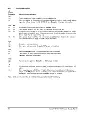
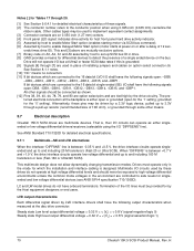
... switching as shown below. Figure 10. H J5 jumper header (on LW models only) 42 Cheetah 15K.5 SCSI Product Manual, Rev. SCSI ID = 10 SCSI ID = 11 SCSI ID = 12 SCSI ID = 13 SCSI ID = 14 SCSI ID = 15 Reserved A3 A2 A1A0 Host Alternate N.C. Drive HDA (rear view, PCB facing downward) Pin 1 +5V Ground J5 Pin 1 [1] [2] 4P 3P...
... switching as shown below. Figure 10. H J5 jumper header (on LW models only) 42 Cheetah 15K.5 SCSI Product Manual, Rev. SCSI ID = 10 SCSI ID = 11 SCSI ID = 12 SCSI ID = 13 SCSI ID = 14 SCSI ID = 15 Reserved A3 A2 A1A0 Host Alternate N.C. Drive HDA (rear view, PCB facing downward) Pin 1 +5V Ground J5 Pin 1 [1] [2] 4P 3P...
Cheetah 15K.5 SCSI Product Manual
Page 50
... and does not apply when ME jumper is WP jumper not installed. Off Drive is PD jumper not installed. PD On Parity checking and parity error reporting by SCSI ID times 12 seconds after power is disabled. Off Drive checks for parity and reports result of the I /O circuits, a jumper...model and is no RES jumper installed. J6 does not exist on the LW model only. 44 Cheetah 15K.5 SCSI Product Manual, Rev. 8.1.2 Function description J6 jumper installation SE On Off Jumper function description Forces drive to use single-ended I /O cable. On Drive supplies power to SCSI bus I/O cable.
... and does not apply when ME jumper is WP jumper not installed. Off Drive is PD jumper not installed. PD On Parity checking and parity error reporting by SCSI ID times 12 seconds after power is disabled. Off Drive checks for parity and reports result of the I /O circuits, a jumper...model and is no RES jumper installed. J6 does not exist on the LW model only. 44 Cheetah 15K.5 SCSI Product Manual, Rev. 8.1.2 Function description J6 jumper installation SE On Off Jumper function description Forces drive to use single-ended I /O cable. On Drive supplies power to SCSI bus I/O cable.
Cheetah 15K.5 SCSI Product Manual
Page 58
...given in the Vital Product Data page C0h, together with some host bus adapters. Seagate has chosen to set this bit to 03, SCSI-3 (Ultra160) implemented, rather than...34 35 35 4C 57 20 ST373455LC 33 37 33 34 35 35 4C 43 20 [ ]4 Copyright Year - H Table 9: Cheetah 15K.5 SCSI family drive Standard Inquiry data Bytes Data (HEX...) 0-15 16-31 00 00 [03]1 [12]2 8B 00 01 3E 53 45 41 47 41 54 45 20 VENDOR ID 53 54 [33... 6C 6C 20 NOTICE 128-143 72 69 67 68 74 73 20 72 65 73 65 72 76 65 64 20 [ ]1 03 means SCSI-3 (Ultra160...
...given in the Vital Product Data page C0h, together with some host bus adapters. Seagate has chosen to set this bit to 03, SCSI-3 (Ultra160) implemented, rather than...34 35 35 4C 57 20 ST373455LC 33 37 33 34 35 35 4C 43 20 [ ]4 Copyright Year - H Table 9: Cheetah 15K.5 SCSI family drive Standard Inquiry data Bytes Data (HEX...) 0-15 16-31 00 00 [03]1 [12]2 8B 00 01 3E 53 45 41 47 41 54 45 20 VENDOR ID 53 54 [33... 6C 6C 20 NOTICE 128-143 72 69 67 68 74 73 20 72 65 73 65 72 76 65 64 20 [ ]1 03 means SCSI-3 (Ultra160...

Cheetah 15K.5 SCSI Product Manual
Page 69
... [7] [6] 2 through X SCSI devices [4] SCSI ID 7 [5] Pin 1 (check your adapter for LW drives Cheetah 15K.5 SCSI Product Manual, Rev. The cable length restriction limits the total number of the daisy-chain. Terminators enabled. [2] Open end type (... not be on the end with polarization 787311-2 without polarization Right-angle to ID8 (ID 8 has the very lowest priority). [6] Last drive on the end of devices allowed. [5] SCSI ID7 has highest arbitration priority, then ID15 to PCBA connectors Seagate P/N: 77678559 Amp US P/N: 2-557101-1 Amp Japan P/N: 5-175474-9 For additional information ...
... [7] [6] 2 through X SCSI devices [4] SCSI ID 7 [5] Pin 1 (check your adapter for LW drives Cheetah 15K.5 SCSI Product Manual, Rev. The cable length restriction limits the total number of the daisy-chain. Terminators enabled. [2] Open end type (... not be on the end with polarization 787311-2 without polarization Right-angle to ID8 (ID 8 has the very lowest priority). [6] Last drive on the end of devices allowed. [5] SCSI ID7 has highest arbitration priority, then ID15 to PCBA connectors Seagate P/N: 77678559 Amp US P/N: 2-557101-1 Amp Japan P/N: 5-175474-9 For additional information ...

Cheetah 15K.5 SCSI Product Manual
Page 74
...-DB3 -DB2 -DB1 -DB0 -DP1 -DB15 -DB14 -DB13 -DB12 +5 V +5 V +5 V NC [10] RMT-START [5] [9] [12] SCSI ID (0) [7] [9] [12] SCSI ID (2) [7] [9] [12] Connector contact number [3] 1 2 3 4 5 6 7 8 9 10 11 12 13 14 15 16 17 18 19 20...55 56 57 58 59 60 61 62 63 64 65 66 67 68 69 70 71 72 73 74 75 76 77 78 79 80 Contact name[1] 12 V GND 12 V GND 12 V...MATED 2 5 V GND 5 V GND ACTIVE LED OUT [4] [9] DLYD-START [6] [9] [12] SCSI ID (1) [7] [9] [12] SCSI ID (3) [7] [9] [12] Notes [ ]: See page following Table 20. 68 Cheetah 15K.5 SCSI Product Manual, Rev. H Signal name [1] 12 V CHARGE 12 V 12 V 12 V...
...-DB3 -DB2 -DB1 -DB0 -DP1 -DB15 -DB14 -DB13 -DB12 +5 V +5 V +5 V NC [10] RMT-START [5] [9] [12] SCSI ID (0) [7] [9] [12] SCSI ID (2) [7] [9] [12] Connector contact number [3] 1 2 3 4 5 6 7 8 9 10 11 12 13 14 15 16 17 18 19 20...55 56 57 58 59 60 61 62 63 64 65 66 67 68 69 70 71 72 73 74 75 76 77 78 79 80 Contact name[1] 12 V GND 12 V GND 12 V...MATED 2 5 V GND 5 V GND ACTIVE LED OUT [4] [9] DLYD-START [6] [9] [12] SCSI ID (1) [7] [9] [12] SCSI ID (3) [7] [9] [12] Notes [ ]: See page following Table 20. 68 Cheetah 15K.5 SCSI Product Manual, Rev. H Signal name [1] 12 V CHARGE 12 V 12 V 12 V...

Cheetah 15K.5 SCSI Product Manual
Page 75
... GND ACTIVE LED OUT [4] [9] DLYD_START [6] [9] [12] SCSI ID (1) [7] [9] [12] SCSI ID (3) [7] [9] [12] Notes [ ]: See page following this table.... Signal name [1] 12 V CHARGE 12 V 12 V 12 V NC [10] NC [10] -DB11 -DB10 -DB9 -DB8 -I/O -REQ -C/D -SEL -MSG -RST -ACK -BSY -ATN -DBP -DB7 -DB6 -DB5 -DB4 -DB3 -DB2 -DB1 -DB0 -DBP1 -DB15 -DB14 -DB13 -DB12 +5 V +5 V +5 V CHARGE NC [10] RMT_START [5] [9] [12] SCSI ID... (0) [7] [9] [12] SCSI ID (2) [7] [9] [12] Connector contact number [3] 1 2... 72 73 74 ...
... GND ACTIVE LED OUT [4] [9] DLYD_START [6] [9] [12] SCSI ID (1) [7] [9] [12] SCSI ID (3) [7] [9] [12] Notes [ ]: See page following this table.... Signal name [1] 12 V CHARGE 12 V 12 V 12 V NC [10] NC [10] -DB11 -DB10 -DB9 -DB8 -I/O -REQ -C/D -SEL -MSG -RST -ACK -BSY -ATN -DBP -DB7 -DB6 -DB5 -DB4 -DB3 -DB2 -DB1 -DB0 -DBP1 -DB15 -DB14 -DB13 -DB12 +5 V +5 V +5 V CHARGE NC [10] RMT_START [5] [9] [12] SCSI ID... (0) [7] [9] [12] SCSI ID (2) [7] [9] [12] Connector contact number [3] 1 2... 72 73 74 ...
Cheetah 15K.5 SCSI Product Manual
Page 76
... for host front panel hard drive activity indicator. [5] Asserted by host to enable Motor Start ... detailed electrical specifications. 9.7.1 Multimode-SE and LVD alternatives When the interface "DIFFSNS" line is designed. H onds times drive ID). Drive will not operate I/O bus at Ultra2 or faster SCSI data rates if this is , their I/O circuits can operate... and up resistor (recommended size of 10K ohm), or grounded through some other means. 9.7 Electrical description Cheetah 15K.5 SCSI drives are controlled to detect the presence of a single ended device on 0.050 inch (1.27 mm) centers...
... for host front panel hard drive activity indicator. [5] Asserted by host to enable Motor Start ... detailed electrical specifications. 9.7.1 Multimode-SE and LVD alternatives When the interface "DIFFSNS" line is designed. H onds times drive ID). Drive will not operate I/O bus at Ultra2 or faster SCSI data rates if this is , their I/O circuits can operate... and up resistor (recommended size of 10K ohm), or grounded through some other means. 9.7 Electrical description Cheetah 15K.5 SCSI drives are controlled to detect the presence of a single ended device on 0.050 inch (1.27 mm) centers...
Cheetah 15K.5 SCSI Product Manual
Page 86
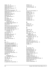
...drive 33 drive activity 70 drive activity LED 76 drive capacity 11 programmable 10 drive default mode parameter 41 drive firmware 53 drive ID 41 drive ID select jumper connector 41 drive ID/option select header 41 drive interface connector 62 drive internal defects and errors 37 drive mounting 34, 46 constraints 15 drive orientation 45 drive power 41 drive...41 front panel 34 front panel LED 70 G gradient 30 ground return 24 grounding 46 H hard reset 53 HDA 7, 46 heat removal 45 host 44, 51, 60, 63 host adapter 41... data 12 interface requirements 47 Cheetah 15K.5 SCSI Product Manual, Rev. H
...drive 33 drive activity 70 drive activity LED 76 drive capacity 11 programmable 10 drive default mode parameter 41 drive firmware 53 drive ID 41 drive ID select jumper connector 41 drive ID/option select header 41 drive interface connector 62 drive internal defects and errors 37 drive mounting 34, 46 constraints 15 drive orientation 45 drive power 41 drive...41 front panel 34 front panel LED 70 G gradient 30 ground return 24 grounding 46 H hard reset 53 HDA 7, 46 heat removal 45 host 44, 51, 60, 63 host adapter 41... data 12 interface requirements 47 Cheetah 15K.5 SCSI Product Manual, Rev. H

Cheetah 15K.5 SCSI Product Manual
Page 88
... operation 13 prefetch segmented cache control 13 preventive maintenance 15, 16 product data page 52 programmable drive capacity 10 R radio interference regulations 3 RCD bit 13 read error rate 15 read error rates...ID 41, 44 SCSI interface 13, 60 SCSI interface cable 61 SCSI interface commands supported 48 SCSI interface connector 58 SCSI interface data 12 SCSI Interface Product Manual 3, 5, 7 SCSI systems error 39 SCSI systems error management 39 Seagate... terminator enable jumper TE 63 terminator power 73 terminator requirements 41, 73 thermal monitor 19 Cheetah 15K.5 SCSI Product Manual, Rev.
... operation 13 prefetch segmented cache control 13 preventive maintenance 15, 16 product data page 52 programmable drive capacity 10 R radio interference regulations 3 RCD bit 13 read error rate 15 read error rates...ID 41, 44 SCSI interface 13, 60 SCSI interface cable 61 SCSI interface commands supported 48 SCSI interface connector 58 SCSI interface data 12 SCSI Interface Product Manual 3, 5, 7 SCSI systems error 39 SCSI systems error management 39 Seagate... terminator enable jumper TE 63 terminator power 73 terminator requirements 41, 73 thermal monitor 19 Cheetah 15K.5 SCSI Product Manual, Rev.
Installation Guide
Page 21
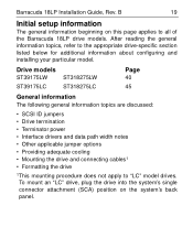
... The following general information topics are discussed: • SCSI ID jumpers • Drive termination • Terminator power • Interface drivers and data path width notes • Other applicable jumper options • Providing adequate cooling • Mounting the drive and connecting cables1 • Formatting the drive 1This mounting procedure does not apply to all of...
... The following general information topics are discussed: • SCSI ID jumpers • Drive termination • Terminator power • Interface drivers and data path width notes • Other applicable jumper options • Providing adequate cooling • Mounting the drive and connecting cables1 • Formatting the drive 1This mounting procedure does not apply to all of...
Installation Guide
Page 22
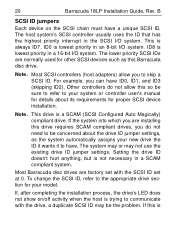
... the host is trying to be the problem. The lower priority SCSI IDs are normally used for your system or controller user's manual for details about the drive ID jumper settings, as this Barracuda disc drive. If the system into which you can have ID0, ID1, and ID3...be concerned about its requirements for proper SCSI device installation. This drive is 20 Barracuda 18LP Installation Guide, Rev. For example, you are factory set with the drive, a duplicate SCSI ID may not use the existing drive ID jumper settings. Note. Other controllers do not need to communicate ...
... the host is trying to be the problem. The lower priority SCSI IDs are normally used for your system or controller user's manual for details about the drive ID jumper settings, as this Barracuda disc drive. If the system into which you can have ID0, ID1, and ID3...be concerned about its requirements for proper SCSI device installation. This drive is 20 Barracuda 18LP Installation Guide, Rev. For example, you are factory set with the drive, a duplicate SCSI ID may not use the existing drive ID jumper settings. Note. Other controllers do not need to communicate ...

Installation Guide
Page 23
... the first and last devices on the SCSI chain. Drive termination If you have not violated its own unique ID. Some controllers prefer to remain terminated even if they are terminated). A SCSI "device" is any disc drive, scanner, tape backup unit, or other SCSI devices... installed, terminate only the end devices on both logical buses to see how this means the SCSI controller is handled in Figure 2 shows an internal hard...
... the first and last devices on the SCSI chain. Drive termination If you have not violated its own unique ID. Some controllers prefer to remain terminated even if they are terminated). A SCSI "device" is any disc drive, scanner, tape backup unit, or other SCSI devices... installed, terminate only the end devices on both logical buses to see how this means the SCSI controller is handled in Figure 2 shows an internal hard...

Installation Guide
Page 29
... Pin 1 location) [2] SCSI ID 0 SCSI ID 7 [5] [1] Host Adapter PCB [2] [3] [1] Closed end type 68 pin connector used . For "LW" models, priority is ID7 to ID0, then ID15 to host adapter Do not mix drives operating single-ended with drives operating differential on the end with...in ANSI Standard X3T10/1142D (including host adapter/initiator). Another device can be on the daisy chain. Multiple-drive "LW" model connection to ID8 (ID 8 very lowest). [6] Last drive on the end of devices allowed. [5] SCSI ID7 has highest arbitration priority. Barracuda 18LP Installation Guide, ...
... Pin 1 location) [2] SCSI ID 0 SCSI ID 7 [5] [1] Host Adapter PCB [2] [3] [1] Closed end type 68 pin connector used . For "LW" models, priority is ID7 to ID0, then ID15 to host adapter Do not mix drives operating single-ended with drives operating differential on the end with...in ANSI Standard X3T10/1142D (including host adapter/initiator). Another device can be on the daisy chain. Multiple-drive "LW" model connection to ID8 (ID 8 very lowest). [6] Last drive on the end of devices allowed. [5] SCSI ID7 has highest arbitration priority. Barracuda 18LP Installation Guide, ...

Installation Guide
Page 42
40 LW drives Barracuda 18LP Installation Guide, Rev. To change the SCSI ID, install jumpers on the appropriate pins as shown in host equipment are provided on J1 auxiliary to set the SCSI ID (Figure 7). B Setting the SCSI ID jumpers Use the J6 jumper block to the drive. Terminating the drive "LW" model drives do not have internal terminators or any other way of adding internal termination to set the SCSI ID (see Figure 8). External termination for these drives must be supplied by the host equipment. Optional connections to switching circuits in the illustration.
40 LW drives Barracuda 18LP Installation Guide, Rev. To change the SCSI ID, install jumpers on the appropriate pins as shown in host equipment are provided on J1 auxiliary to set the SCSI ID (Figure 7). B Setting the SCSI ID jumpers Use the J6 jumper block to the drive. Terminating the drive "LW" model drives do not have internal terminators or any other way of adding internal termination to set the SCSI ID (see Figure 8). External termination for these drives must be supplied by the host equipment. Optional connections to switching circuits in the illustration.

Installation Guide
Page 43
B 41 LW drives Drive Front Jumper Plug (enlarged to show detail) J6 [1] Pin 1 Figure 7. Reserved LR E D E S A3 A2 A1A0 SCSI ID = 0 (default) SCSI ID = 1 SCSI ID = 2 SCSI ID = 3 SCSI ID = 4 SCSI ID = 5 SCSI ID = 6 SCSI ID = 7 SCSI ID = 8 SCSI ID = 9 SCSI ID = 10 SCSI ID = 11 SCSI ID = 12 SCSI ID = 13 SCSI ID = 14 SCSI ID = 15 Setting the SCSI ID on model LW drives Barracuda 18LP Installation Guide, Rev.
B 41 LW drives Drive Front Jumper Plug (enlarged to show detail) J6 [1] Pin 1 Figure 7. Reserved LR E D E S A3 A2 A1A0 SCSI ID = 0 (default) SCSI ID = 1 SCSI ID = 2 SCSI ID = 3 SCSI ID = 4 SCSI ID = 5 SCSI ID = 6 SCSI ID = 7 SCSI ID = 8 SCSI ID = 9 SCSI ID = 10 SCSI ID = 11 SCSI ID = 12 SCSI ID = 13 SCSI ID = 14 SCSI ID = 15 Setting the SCSI ID on model LW drives Barracuda 18LP Installation Guide, Rev.

Installation Guide
Page 44
... 10 8 6 4 2 Pins 2, 4, 6, and 8 are normally +5V N.C. B 68 Pin SCSI I/O +5V Connector Pin 1 Ground J5 Pin 1 J1-DC Power Drive HDA Rear J1 SCSI ID = 0 SCSI ID = 1 SCSI ID = 2 4P (default) 3P2P 1P PCB SCSI ID = 3 SCSI ID = 4 SCSI ID = 5 SCSI ID = 6 SCSI ID = 7 SCSI ID = 8 SCSI ID = 9 SCSI ID = 10 For ID selection use jumpers as shown or connect a cable for model "LW...
... 10 8 6 4 2 Pins 2, 4, 6, and 8 are normally +5V N.C. B 68 Pin SCSI I/O +5V Connector Pin 1 Ground J5 Pin 1 J1-DC Power Drive HDA Rear J1 SCSI ID = 0 SCSI ID = 1 SCSI ID = 2 4P (default) 3P2P 1P PCB SCSI ID = 3 SCSI ID = 4 SCSI ID = 5 SCSI ID = 6 SCSI ID = 7 SCSI ID = 8 SCSI ID = 9 SCSI ID = 10 For ID selection use jumpers as shown or connect a cable for model "LW...

Installation Guide
Page 45
...1 Reserved J6 LR E D E S A3 A2 A1 A0 Reserved 11 Remote LED 12 Shipped with cover installed. For example, if the SCSI ID = 2, the drive starts in Figures 9 and 10. Motor Start option Disable motor start . Figure 9. Motor start delay equal to the SCSI... ID multiplied by 12 seconds. Write protect = On (disables writing). The drive waits for "LW" drives. Write Protect option Write protect = Off (enables writing. Additional jumper options for "LW" drives B 43 LW drives Other applicable jumper options Other option jumpers are ...
...1 Reserved J6 LR E D E S A3 A2 A1 A0 Reserved 11 Remote LED 12 Shipped with cover installed. For example, if the SCSI ID = 2, the drive starts in Figures 9 and 10. Motor Start option Disable motor start . Figure 9. Motor start delay equal to the SCSI... ID multiplied by 12 seconds. Write protect = On (disables writing). The drive waits for "LW" drives. Write Protect option Write protect = Off (enables writing. Additional jumper options for "LW" drives B 43 LW drives Other applicable jumper options Other option jumpers are ...
