Barracuda 7200.10 PATA Product Manual
Page 3
... 32 3.0 Configuring and mounting the drive 33 3.1 Handling and static discharge precautions 33 3.2 Breather filter hole precautions 34 3.3 Jumper settings 35 3.3.1 Master/slave configuration 35... 3.3.2 Cable-select option 35 3.3.3 Ultra ATA/100 cable 36 3.4 Drive mounting 36 4.0 ATA interface 39 4.1 ATA interface signals and connector pins 39 4.1.1 Supported ATA commands 40 4.1.2 Identify Device command 42 4.1.3 Set Features command 45 4.1.4 S.M.A.R.T. commands 46 5.0 Seagate Technology support services 47 Barracuda...
... 32 3.0 Configuring and mounting the drive 33 3.1 Handling and static discharge precautions 33 3.2 Breather filter hole precautions 34 3.3 Jumper settings 35 3.3.1 Master/slave configuration 35... 3.3.2 Cable-select option 35 3.3.3 Ultra ATA/100 cable 36 3.4 Drive mounting 36 4.0 ATA interface 39 4.1 ATA interface signals and connector pins 39 4.1.1 Supported ATA commands 40 4.1.2 Identify Device command 42 4.1.3 Set Features command 45 4.1.4 S.M.A.R.T. commands 46 5.0 Seagate Technology support services 47 Barracuda...
Barracuda 7200.10 PATA Product Manual
Page 5
Figure 2. Figure 4. Figure 5. Typical 5V startup and operation current profile 24 Typical 12V startup and operation current profile 24 Breather filter hole location 34 Master/slave jumper settings 35 Ultra ATA cable connectors 36 Mounting dimensions for 200-750 GB models 37 Mounting dimensions for 40-160 GB models 38 I/O pins and supported ATA signals 39 Barracuda 7200.10 PATA Product Manual, Rev. F iii Figure 3. List of Figures Figure 1. Figure 7. Figure 6. Figure 8.
Figure 2. Figure 4. Figure 5. Typical 5V startup and operation current profile 24 Typical 12V startup and operation current profile 24 Breather filter hole location 34 Master/slave jumper settings 35 Ultra ATA cable connectors 36 Mounting dimensions for 200-750 GB models 37 Mounting dimensions for 40-160 GB models 38 I/O pins and supported ATA signals 39 Barracuda 7200.10 PATA Product Manual, Rev. F iii Figure 3. List of Figures Figure 1. Figure 7. Figure 6. Figure 8.
Barracuda 7200.10 PATA Product Manual
Page 41
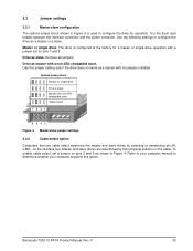
... 3.3.2 Cable-select option Computers that use cable select determine the master and slave drives by their physical position on pins 5 and 6 as a master or a slave. Barracuda 7200.10 PATA Product Manual, Rev. F 35 3.3 Jumper settings 3.3.1 Master/slave configuration The options jumper block shown in Figure 4. Use this option. To enable cable select, set on...
... 3.3.2 Cable-select option Computers that use cable select determine the master and slave drives by their physical position on pins 5 and 6 as a master or a slave. Barracuda 7200.10 PATA Product Manual, Rev. F 35 3.3 Jumper settings 3.3.1 Master/slave configuration The options jumper block shown in Figure 4. Use this option. To enable cable select, set on...
Barracuda 7200.10 PATA Product Manual
Page 56
...41 S.M.A.R.T. F commands 46 S.M.A.R.T. Disable Operations 41 S.M.A.R.T. Execute Offline 41 Barracuda 7200.10 PATA Product Manual, Rev. Idle and Standby timers 25 Idle..., 39 interface signals 39 interference 31 internal data-transfer rate OD 21 ISO document 7779 28 J jumper settings 35 K Korean RRL 31 L LBA mode 20 length 21 logical geometry 20 M maintenance 30...35 maximum temperature 26 Mean Time Between Failures 30 measurement locations 26 modes 39 monitoring 1 mounting the drive 33, 36 MTBF 30 N noise 24 nominal power 3 nonoperating shock 27 nonoperating vibration 27 Nonrecoverable...
...41 S.M.A.R.T. F commands 46 S.M.A.R.T. Disable Operations 41 S.M.A.R.T. Execute Offline 41 Barracuda 7200.10 PATA Product Manual, Rev. Idle and Standby timers 25 Idle..., 39 interface signals 39 interference 31 internal data-transfer rate OD 21 ISO document 7779 28 J jumper settings 35 K Korean RRL 31 L LBA mode 20 length 21 logical geometry 20 M maintenance 30...35 maximum temperature 26 Mean Time Between Failures 30 measurement locations 26 modes 39 monitoring 1 mounting the drive 33, 36 MTBF 30 N noise 24 nominal power 3 nonoperating shock 27 nonoperating vibration 27 Nonrecoverable...
Serial ATA - A Comparison with Ultra ATA Technology (57K, PDF)
Page 6
...6". Basic Reliability Support The ATA/ATAPI-6 revision includes support for upcoming 2.5" hard disk drives. Control signal transmissions are at most 0.25" wide and can be used unmodified on all hard-drive sizes available today, negating the need for Dedicated Bandwidth Serial ATA uses a ...point-to ATA/ATAPI-5 or earlier devices. Beyond Better Signaling Characteristics... Though Ultra ATA supports a command queuing algorithm, it is connected to Point Connections for master/slave jumper...
...6". Basic Reliability Support The ATA/ATAPI-6 revision includes support for upcoming 2.5" hard disk drives. Control signal transmissions are at most 0.25" wide and can be used unmodified on all hard-drive sizes available today, negating the need for Dedicated Bandwidth Serial ATA uses a ...point-to ATA/ATAPI-5 or earlier devices. Beyond Better Signaling Characteristics... Though Ultra ATA supports a command queuing algorithm, it is connected to Point Connections for master/slave jumper...


