
SAS and SATA: Multiple Benefits of Unified Storage (334K, PDF)
Page 2
...a SAS infrastructure (HBAs, backplanes, cabling, and so forth) that is needed, more SATA drives and SAS RAID backplanes are ideal for Capacity SATA Drives Device SAS (15K RPM, 10K RPM...SATA became a central component of SATA drives with high availability to multiple, concurrent users), adding high-performance SAS drives is simple: SAS hard drives deliver the speed, reliability and scalability demanded...combining low cost per GB and greater reliability and scalability than their parallel ATA ancestors. Combining SATA with low-cost, high-capacity SATA drives. they had hamstrung ...
...a SAS infrastructure (HBAs, backplanes, cabling, and so forth) that is needed, more SATA drives and SAS RAID backplanes are ideal for Capacity SATA Drives Device SAS (15K RPM, 10K RPM...SATA became a central component of SATA drives with high availability to multiple, concurrent users), adding high-performance SAS drives is simple: SAS hard drives deliver the speed, reliability and scalability demanded...combining low cost per GB and greater reliability and scalability than their parallel ATA ancestors. Combining SATA with low-cost, high-capacity SATA drives. they had hamstrung ...
SAS and SATA: Multiple Benefits of Unified Storage (334K, PDF)
Page 3
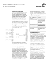
... already have extensive transactional (online) storage application needs, which they've historically addressed with compact cabling For many firms, the optimal blend of performance-optimized storage and capacityoptimized storage is increasingly concerned with...SCSI Drive RAID P-SCSI Drive P-SCSI RAID Drive P-SCSI Drive RAID SATA Drive SATA Drive RAID SATA Drive SATA Drive Server Server Expander JBOD SAS Drive SAS Drive SAS Drive SAS Drive SAS Drive SATA Drive SATA Drive SATA Drive SATA Drive SATA Drive Figure 3. Beyond the obvious efficiency of specifying the optimal hard drive for...
... already have extensive transactional (online) storage application needs, which they've historically addressed with compact cabling For many firms, the optimal blend of performance-optimized storage and capacityoptimized storage is increasingly concerned with...SCSI Drive RAID P-SCSI Drive P-SCSI RAID Drive P-SCSI Drive RAID SATA Drive SATA Drive RAID SATA Drive SATA Drive Server Server Expander JBOD SAS Drive SAS Drive SAS Drive SAS Drive SAS Drive SATA Drive SATA Drive SATA Drive SATA Drive SATA Drive Figure 3. Beyond the obvious efficiency of specifying the optimal hard drive for...
Cheetah 10K.7 SCSI Product Manual
Page 8
... Mechanical specifications 38 7.0 Defect and error management 41 7.1 Drive internal defects 41 7.2 Drive error recovery procedures 41 7.3 SCSI systems errors 43 7.4 Background Media Scan 44 7.4.1 Media...cable and connector 65 9.6.2 SCSI interface physical description 67 9.6.3 SCSI interface cable requirements 68 9.6.4 Mating connectors 68 9.7 Electrical description 80 9.7.1 Multimode-SE and LVD alternatives 80 9.8 Terminator requirements 83 9.9 Terminator power 83 9.10 Disc drive SCSI timing 84 9.11 Drive activity LED 86 10.0 Seagate Technology support services 87 vi Cheetah...
... Mechanical specifications 38 7.0 Defect and error management 41 7.1 Drive internal defects 41 7.2 Drive error recovery procedures 41 7.3 SCSI systems errors 43 7.4 Background Media Scan 44 7.4.1 Media...cable and connector 65 9.6.2 SCSI interface physical description 67 9.6.3 SCSI interface cable requirements 68 9.6.4 Mating connectors 68 9.7 Electrical description 80 9.7.1 Multimode-SE and LVD alternatives 80 9.8 Terminator requirements 83 9.9 Terminator power 83 9.10 Disc drive SCSI timing 84 9.11 Drive activity LED 86 10.0 Seagate Technology support services 87 vi Cheetah...
Cheetah 10K.7 SCSI Product Manual
Page 9
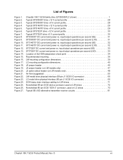
...Figure 23. Cheetah 10K.7 SCSI family drive (ST3300007LC shown 1 Typical ST3300007 drive +12 V current profile 28 Typical ST3300007 drive +5 V current profile 28 Typical ST3146707 drive +12 V current profile 29 Typical ST3146707 drive +5 V current profile 29 Typical ST373207 drive +12 V current profile 30 Typical ST373207 drive +5 V ...daisy chain interface cabling for LW drives 71 Nonshielded 68-pin SCSI device connector used on LW drives 72 Nonshielded 80-pin SCSI "SCA-2" connector, used on LC drives 73 Typical SE-LVD alternative transmitter receiver circuits 81 Cheetah 10K.7 SCSI ...
...Figure 23. Cheetah 10K.7 SCSI family drive (ST3300007LC shown 1 Typical ST3300007 drive +12 V current profile 28 Typical ST3300007 drive +5 V current profile 28 Typical ST3146707 drive +12 V current profile 29 Typical ST3146707 drive +5 V current profile 29 Typical ST373207 drive +12 V current profile 30 Typical ST373207 drive +5 V ...daisy chain interface cabling for LW drives 71 Nonshielded 68-pin SCSI device connector used on LW drives 72 Nonshielded 80-pin SCSI "SCA-2" connector, used on LC drives 73 Typical SE-LVD alternative transmitter receiver circuits 81 Cheetah 10K.7 SCSI ...
Cheetah 10K.7 SCSI Product Manual
Page 13
... mounted in an enclosure that equipment operating in the same system as the drive or external to meet the requirements of Section 8.4. 2.1 Standards The Cheetah 10K.7 SCSI family complies with Seagate standards as delivered, is not required to the system does not adversely affect...Department of Communications. Shielded I /O cables are external to the enclosure, shielded cables should be required if the enclosure does not provide adequate shielding. See Table 2, DC power requirements. Cheetah 10K.7 SCSI Product Manual, Rev. As such, the drive is not subject to achieve optimum ...
... mounted in an enclosure that equipment operating in the same system as the drive or external to meet the requirements of Section 8.4. 2.1 Standards The Cheetah 10K.7 SCSI family complies with Seagate standards as delivered, is not required to the system does not adversely affect...Department of Communications. Shielded I /O cables are external to the enclosure, shielded cables should be required if the enclosure does not provide adequate shielding. See Table 2, DC power requirements. Cheetah 10K.7 SCSI Product Manual, Rev. As such, the drive is not subject to achieve optimum ...
Cheetah 10K.7 SCSI Product Manual
Page 23
... Mode Select command with a Read command is retrieved from the buffer (if it is used in each is no cable loss. [4] Access to exceed 25 seconds. The buffer can enhance system performance. The drive supports a maximum of DC power. After the Motor Start Command has been received the...bytes per sector) is there), before any disc access Cheetah 10K.7 SCSI Product Manual, Rev. However, in actual operation the prefetch feature overlaps cache operation somewhat as is noted in the drive can also be used herein refers to the drive buffer storage space when it is odd, then n-1 ...
... Mode Select command with a Read command is retrieved from the buffer (if it is used in each is no cable loss. [4] Access to exceed 25 seconds. The buffer can enhance system performance. The drive supports a maximum of DC power. After the Motor Start Command has been received the...bytes per sector) is there), before any disc access Cheetah 10K.7 SCSI Product Manual, Rev. However, in actual operation the prefetch feature overlaps cache operation somewhat as is noted in the drive can also be used herein refers to the drive buffer storage space when it is odd, then n-1 ...
Cheetah 10K.7 SCSI Product Manual
Page 37
...frequencies covering a band from a common supply, careful consideration for LC models. The current during power-up . 5. three-quarters to the drive. Minimum current loading for each device. 4. No terminator power. 6.2.1 Conducted noise immunity Noise is as a periodic and random distribution of... pp from 8 KHz to 5 MHz. 6.2.2 Power sequencing The drive does not require power sequencing. Note. Spindle begins to speed and the head-arm restraint is performed. See Note 1 of the peripheral I/O cables. Cheetah 10K.7 SCSI Product Manual, Rev. Where multiple units are performed...
...frequencies covering a band from a common supply, careful consideration for LC models. The current during power-up . 5. three-quarters to the drive. Minimum current loading for each device. 4. No terminator power. 6.2.1 Conducted noise immunity Noise is as a periodic and random distribution of... pp from 8 KHz to 5 MHz. 6.2.2 Power sequencing The drive does not require power sequencing. Note. Spindle begins to speed and the head-arm restraint is performed. See Note 1 of the peripheral I/O cables. Cheetah 10K.7 SCSI Product Manual, Rev. Where multiple units are performed...
Cheetah 10K.7 SCSI Product Manual
Page 55
...data buses. • If multiple devices are changed after power has been applied, recycle the drive power to Figures 18, 19, and 20. If necessary see Section 10 for Seagate support services telephone numbers. • Do not remove the manufacturer's installed labels from the ... host I/O signals on . Note. Formatting Drives are not normally needed . • Ensure that is not the same as the manufacturer labels contain information required when servicing the product. Cheetah 10K.7 SCSI Product Manual, Rev. Some users connect cables to power on the LC model. 8.0 Installation...
...data buses. • If multiple devices are changed after power has been applied, recycle the drive power to Figures 18, 19, and 20. If necessary see Section 10 for Seagate support services telephone numbers. • Do not remove the manufacturer's installed labels from the ... host I/O signals on . Note. Formatting Drives are not normally needed . • Ensure that is not the same as the manufacturer labels contain information required when servicing the product. Cheetah 10K.7 SCSI Product Manual, Rev. Some users connect cables to power on the LC model. 8.0 Installation...
Cheetah 10K.7 SCSI Product Manual
Page 57
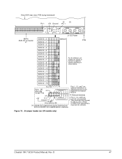
... connections to switching circuits in host equipment to host supplied optional usage plug. J5 jumper header (on LW models only) Cheetah 10K.7 SCSI Product Manual, Rev. They are normally not grounded. Drive HDA (rear view, PCB facing downward) J5 [1] Pin 1 +5V Ground Pin 1 4P 3P 2P 1P J1-DC Power 68 Pin... SCSI ID = 11 SCSI ID = 12 SCSI ID = 13 (default) PCB For ID selection use jumpers as shown or connect a cable for 250 ms after a Reset or PWR ON to allow drive to read SCSI ID selected. SCSI ID = 14 SCSI ID = 15 Reserved A3 A2 A1A0 Host [4] Alternate Usage Plug N.C. 11...
... connections to switching circuits in host equipment to host supplied optional usage plug. J5 jumper header (on LW models only) Cheetah 10K.7 SCSI Product Manual, Rev. They are normally not grounded. Drive HDA (rear view, PCB facing downward) J5 [1] Pin 1 +5V Ground Pin 1 4P 3P 2P 1P J1-DC Power 68 Pin... SCSI ID = 11 SCSI ID = 12 SCSI ID = 13 (default) PCB For ID selection use jumpers as shown or connect a cable for 250 ms after a Reset or PWR ON to allow drive to read SCSI ID selected. SCSI ID = 14 SCSI ID = 15 Reserved A3 A2 A1A0 Host [4] Alternate Usage Plug N.C. 11...
Cheetah 10K.7 SCSI Product Manual
Page 58
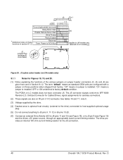
...9, 11-12 or J6 pins 13-20. [6] Connect an external Drive Activity LED to J6 pins 11 and 12 (see Figure 18), or to SFF-8009 Revision 2.0, Unitized Connector for Cabled Drives, signal assignments for auxiliary connectors. [2] These signals are given here ... power source, through an appropriately sized current limiting resistor. J2 option select header (on LW models only) 8.1.1 Notes for the J6 connection. 48 Cheetah 10K.7 SCSI Product Manual, Rev. reserved on LC models does not have connector J5. "Off" means no jumper is installed. D J2 Pin 1 RR Jumper S D M W P ...
...9, 11-12 or J6 pins 13-20. [6] Connect an external Drive Activity LED to J6 pins 11 and 12 (see Figure 18), or to SFF-8009 Revision 2.0, Unitized Connector for Cabled Drives, signal assignments for auxiliary connectors. [2] These signals are given here ... power source, through an appropriately sized current limiting resistor. J2 option select header (on LW models only) 8.1.1 Notes for the J6 connection. 48 Cheetah 10K.7 SCSI Product Manual, Rev. reserved on LC models does not have connector J5. "Off" means no jumper is installed. D J2 Pin 1 RR Jumper S D M W P ...
Cheetah 10K.7 SCSI Product Manual
Page 59
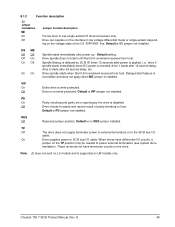
... and reports result of the I/O "DIFFSNS" line. On Drive supplies power to SCSI bus I /O cable. Default is supported on the voltage state of parity checking to host. Cheetah 10K.7 SCSI Product Manual, Rev. Off Drive is SE jumper not installed. Default is not write protected. Drive spindle starts when Start Unit command received from host...
... and reports result of the I/O "DIFFSNS" line. On Drive supplies power to SCSI bus I /O cable. Default is supported on the voltage state of parity checking to host. Cheetah 10K.7 SCSI Product Manual, Rev. Off Drive is SE jumper not installed. Default is not write protected. Drive spindle starts when Start Unit command received from host...

Cheetah 10K.7 SCSI Product Manual
Page 74
... data transfer periods supported In the following , while the SCSI operational aspects of Seagate drive interfaces are negotiated to 0 (asynchronous transfer). 9.6 Physical interface This section describes the connectors, cables, signals, terminators and bus timing of the DC and SCSI I/O interface. Offsets...M is the synchronous period value (in the SCSI Interface Product Manual. 64 Cheetah 10K.7 SCSI Product Manual, Rev. Details of the DC power connector, SCSI interface connector, drive select headers, and option select headers. See the section on wide bus 320...
... data transfer periods supported In the following , while the SCSI operational aspects of Seagate drive interfaces are negotiated to 0 (asynchronous transfer). 9.6 Physical interface This section describes the connectors, cables, signals, terminators and bus timing of the DC and SCSI I/O interface. Offsets...M is the synchronous period value (in the SCSI Interface Product Manual. 64 Cheetah 10K.7 SCSI Product Manual, Rev. Details of the DC power connector, SCSI interface connector, drive select headers, and option select headers. See the section on wide bus 320...
Cheetah 10K.7 SCSI Product Manual
Page 75
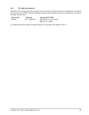
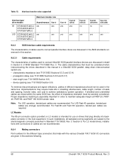
9.6.1 DC cable and connector LW model drives receive DC power through a 4-pin connector (see Figure 24 for pin assignment) mounted at the rear of cable 14 AWG Connector MP 1-480424-0 Contacts (20-14 AWG) AMP 60619-4 (Loose Piece) AMP 61117-4 (Strip) LC model drives receive power through the 80-pin I/O connector. Type of the main PCBA. Cheetah 10K.7 SCSI Product Manual, Rev. Recommended part numbers of the mating connector are listed below, but equivalent parts may be used. D 65 See Tables 16 and 17.
9.6.1 DC cable and connector LW model drives receive DC power through a 4-pin connector (see Figure 24 for pin assignment) mounted at the rear of cable 14 AWG Connector MP 1-480424-0 Contacts (20-14 AWG) AMP 60619-4 (Loose Piece) AMP 61117-4 (Strip) LC model drives receive power through the 80-pin I/O connector. Type of the main PCBA. Cheetah 10K.7 SCSI Product Manual, Rev. Recommended part numbers of the mating connector are listed below, but equivalent parts may be used. D 65 See Tables 16 and 17.
Cheetah 10K.7 SCSI Product Manual
Page 77
... that can be enabled by the end user or designers of the equipment into which the drives will be used. D 67 9.6.2 SCSI interface physical description Cheetah 10K.7 SCSI drives support the physical interface requirements of the Ultra320 SCSI Parallel Interface-4 (SPI-4), and operate compatibly...in the same mode, either SE or LVD, but not a mixture of several drives, so no cables beyond the bulkhead connectors should be connected in a daisy chain by the various drive models defined in this manual support single-ended and low voltage differential physical interconnects (hereafter...
... that can be enabled by the end user or designers of the equipment into which the drives will be used. D 67 9.6.2 SCSI interface physical description Cheetah 10K.7 SCSI drives support the physical interface requirements of the Ultra320 SCSI Parallel Interface-4 (SPI-4), and operate compatibly...in the same mode, either SE or LVD, but not a mixture of several drives, so no cables beyond the bulkhead connectors should be connected in a daisy chain by the various drive models defined in this manual support single-ended and low voltage differential physical interconnects (hereafter...
Cheetah 10K.7 SCSI Product Manual
Page 78
.... LC Models The 80-pin connector option provided on LC models is especially important in shielding effectiveness, cable length, number of different impedances should not be carefully considered. For LC model drives, installations with the various Cheetah 10K.7 SCSI I/O connectors are : • characteristic impedance (see T10/1365D Sections 6.3.3 and 6.3.4) • propagation delay (see...
.... LC Models The 80-pin connector option provided on LC models is especially important in shielding effectiveness, cable length, number of different impedances should not be carefully considered. For LC model drives, installations with the various Cheetah 10K.7 SCSI I/O connectors are : • characteristic impedance (see T10/1365D Sections 6.3.3 and 6.3.4) • propagation delay (see...
Cheetah 10K.7 SCSI Product Manual
Page 79
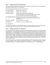
...26). I/O connection using a cable is a nonshielded 68-conductor ... drives The...cable/connector should be allowed...drives. To obtain this connector. D 69 To insure that both drive connector and host equipment mating connector mate properly, both drive...drive interface connector(s) should especially not be used on cable ends or in cable...cables should be controlled and therefore could not be strictly designed according to the drive. Recommended mating flat cable...cable with adjacent contacts 0.050 inch (1.27 mm) apart. 9.6.4.1 Mating connectors for LW model drives The nonshielded cable...
...26). I/O connection using a cable is a nonshielded 68-conductor ... drives The...cable/connector should be allowed...drives. To obtain this connector. D 69 To insure that both drive connector and host equipment mating connector mate properly, both drive...drive interface connector(s) should especially not be used on cable ends or in cable...cables should be controlled and therefore could not be strictly designed according to the drive. Recommended mating flat cable...cable with adjacent contacts 0.050 inch (1.27 mm) apart. 9.6.4.1 Mating connectors for LW model drives The nonshielded cable...

Cheetah 10K.7 SCSI Product Manual
Page 81
... Closed end type 68-pin connector used . D 71 The cable length restriction limits the total number of devices allowed. [5] SCSI ID7 has highest arbitration priority, then ID15 to ID8 (ID 8 has the very lowest priority). [6] Last drive on the end of the bus. Figure 24. LW/LWV Model... Terminator [7] [6] 2 through X SCSI devices [4] SCSI ID 7 [5] Pin 1 [2] (check your adapter for LW drives Cheetah 10K.7 SCSI Product Manual, Rev.
... Closed end type 68-pin connector used . D 71 The cable length restriction limits the total number of devices allowed. [5] SCSI ID7 has highest arbitration priority, then ID15 to ID8 (ID 8 has the very lowest priority). [6] Last drive on the end of the bus. Figure 24. LW/LWV Model... Terminator [7] [6] 2 through X SCSI devices [4] SCSI ID 7 [5] Pin 1 [2] (check your adapter for LW drives Cheetah 10K.7 SCSI Product Manual, Rev.

Cheetah 10K.7 SCSI Product Manual
Page 84
Table 14: LW 68-conductor single-ended (SE) P cable signal/pin assignments [11] Note. D Note: A minus sign preceding a signal name indicates that signal is active low. Signal name [1] GND GND ... 2 3 4 5 6 7 8 9 10 11 12 13 14 15 16 17 18 19 20 21 22 23 24 25 26 27 28 29 30 31 32 33 34 Cable conductor number [2] 1 2 3 4 5 6 7 8 9 10 11 12 13 14 15 16 17 18 19 20 21 22 23 24 25 26 27 28 29 30... Reserved GND -ATN GND -BSY -ACK -RST -MSG -SEL -C/D -REQ -I/O -DB8 -DB9 -DB10 -DB11 Notes [ ]: See page following Table 17. 74 Cheetah 10K.7 SCSI Product Manual, Rev.
Table 14: LW 68-conductor single-ended (SE) P cable signal/pin assignments [11] Note. D Note: A minus sign preceding a signal name indicates that signal is active low. Signal name [1] GND GND ... 2 3 4 5 6 7 8 9 10 11 12 13 14 15 16 17 18 19 20 21 22 23 24 25 26 27 28 29 30 31 32 33 34 Cable conductor number [2] 1 2 3 4 5 6 7 8 9 10 11 12 13 14 15 16 17 18 19 20 21 22 23 24 25 26 27 28 29 30... Reserved GND -ATN GND -BSY -ACK -RST -MSG -SEL -C/D -REQ -I/O -DB8 -DB9 -DB10 -DB11 Notes [ ]: See page following Table 17. 74 Cheetah 10K.7 SCSI Product Manual, Rev.

Cheetah 10K.7 SCSI Product Manual
Page 85
Table 15: LW 68-conductor LVD P cable signal/pin assignments [11] Note. D 75 Signal name [1] +DB12 +DB13 +DB14 +DB15 +DBP1 +DB0 +DB1 +DB2 +DB3 +DB4 ... 5 6 7 8 9 10 11 12 13 14 15 16 17 18 19 20 21 22 23 24 25 26 27 28 29 30 31 32 33 34 Cable conductor number [2] 1 2 3 4 5 6 7 8 9 10 11 12 13 14 15 16 17 18 19 20 21 22 23 24 25 26 27 ... -BSY -ACK -RST -MSG -SEL -C/D -REQ -I/O -DB8 -DB9 -DB10 -DB11 Notes [ ]: See page following Table 17. Cheetah 10K.7 SCSI Product Manual, Rev. Note: A minus sign preceding a signal name indicates that signal is active low.
Table 15: LW 68-conductor LVD P cable signal/pin assignments [11] Note. D 75 Signal name [1] +DB12 +DB13 +DB14 +DB15 +DBP1 +DB0 +DB1 +DB2 +DB3 +DB4 ... 5 6 7 8 9 10 11 12 13 14 15 16 17 18 19 20 21 22 23 24 25 26 27 28 29 30 31 32 33 34 Cable conductor number [2] 1 2 3 4 5 6 7 8 9 10 11 12 13 14 15 16 17 18 19 20 21 22 23 24 25 26 27 ... -BSY -ACK -RST -MSG -SEL -C/D -REQ -I/O -DB8 -DB9 -DB10 -DB11 Notes [ ]: See page following Table 17. Cheetah 10K.7 SCSI Product Manual, Rev. Note: A minus sign preceding a signal name indicates that signal is active low.
Cheetah 10K.7 SCSI Product Manual
Page 90
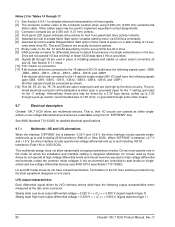
... -DB12, -DB13, -DB14, -DB15, and -DBP1. All other means. 9.7 Electrical description Cheetah 10K.7 SCSI drives are used by the drive circuitry. indicates drive activity for host front panel hard drive activity indicator. [5] Asserted by host to safe levels for singleended and low voltage differential devices (see... setting). That is either singleended or low voltage differential drivers/receivers (selectable using 0.025-inch (0.635 mm) centerline flat ribbon cable. This and [3] above are mutually exclusive options. [7] Binary code on A3, A2, A1 and A0 asserted by a 3.3V...
... -DB12, -DB13, -DB14, -DB15, and -DBP1. All other means. 9.7 Electrical description Cheetah 10K.7 SCSI drives are used by the drive circuitry. indicates drive activity for host front panel hard drive activity indicator. [5] Asserted by host to safe levels for singleended and low voltage differential devices (see... setting). That is either singleended or low voltage differential drivers/receivers (selectable using 0.025-inch (0.635 mm) centerline flat ribbon cable. This and [3] above are mutually exclusive options. [7] Binary code on A3, A2, A1 and A0 asserted by a 3.3V...

