Schwinn 411 Elliptical Assembly

View Results Below
Free Schwinn 411 Elliptical manuals!
Problems with Schwinn 411 Elliptical?
Ask a Question
Free Schwinn 411 Elliptical manuals!
Problems with Schwinn 411 Elliptical?
Ask a Question
Related Manual Pages

Related Videos

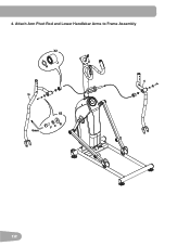
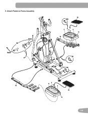
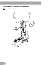
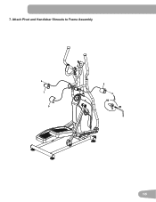
Schwinn 411 Elliptical Assembly Instructions (Full Step by Step Assembly Instruction Guide)
Duration: 6:39
Total Views: 5,567
Duration: 6:39
Total Views: 5,567
Similar Questions

Crank / Pulley Assembly Graze The Shroud
When I start spinning the crank / pulley assembly graze the shroud. I checked and adjusted all conne...
When I start spinning the crank / pulley assembly graze the shroud. I checked and adjusted all conne...
(Posted by morosmarcos 2 years ago)

Brake Assembly On The Schwinn Ic Stationary Bike, 2012 Model
How do I attach the brake assembly on a Schwinn IC Stationary Bike, 2012 model. Are there any drawin...
How do I attach the brake assembly on a Schwinn IC Stationary Bike, 2012 model. Are there any drawin...
(Posted by rickdesorda 9 years ago)

Power Plug Assembly Replacement
Hi..I need to replace the Power Plug Assembly on my Schwinn SR23 Exercise Bike. What is the easiest ...
Hi..I need to replace the Power Plug Assembly on my Schwinn SR23 Exercise Bike. What is the easiest ...
(Posted by chchar 9 years ago)