Service Manual
Page 2
... opening the unit to check or repair electrical parts and wiring. • Keep your job to check that no metal scraps or bits of the flare and union tubes before starting the test run inside the unit being serviced. Escaped refrigerant gas, on the air conditioner can produce dangerously toxic gas. 2 Loose wiring...
... opening the unit to check or repair electrical parts and wiring. • Keep your job to check that no metal scraps or bits of the flare and union tubes before starting the test run inside the unit being serviced. Escaped refrigerant gas, on the air conditioner can produce dangerously toxic gas. 2 Loose wiring...

Service Manual
Page 3
...Compressor Malfunction 62 9-6. Tools Specifically for R410A 61 9-4. Tubing Installation Procedures 61 9-5. In Case of Each Part 54 8-5. Refrigerant Flow Diagram 19 5. Trouble Diagnosis by Error Monitop Lamps 52 8-3. REFRIGERANT R410A: SPECIAL... ...6 2-2. Other Component Specifications 15 3. REFRIGERANT FLOW DIAGRAM 4-1. Temperature Charts ...22 5-2. Cooling Capacity ...36 5-3. Cooling Capacity (Low Ambient 39 6. ELECTRICAL DATA 6-1. Protective Functions ...49 8. Trouble Diagnosis of New Refrigerant R410A 59 9-2. Characteristics of Fan Motor 58 ...
...Compressor Malfunction 62 9-6. Tools Specifically for R410A 61 9-4. Tubing Installation Procedures 61 9-5. In Case of Each Part 54 8-5. Refrigerant Flow Diagram 19 5. Trouble Diagnosis by Error Monitop Lamps 52 8-3. REFRIGERANT R410A: SPECIAL... ...6 2-2. Other Component Specifications 15 3. REFRIGERANT FLOW DIAGRAM 4-1. Temperature Charts ...22 5-2. Cooling Capacity ...36 5-3. Cooling Capacity (Low Ambient 39 6. ELECTRICAL DATA 6-1. Protective Functions ...49 8. Trouble Diagnosis of New Refrigerant R410A 59 9-2. Characteristics of Fan Motor 58 ...

Service Manual
Page 12
... / 1,700W FV50S ... 1.91 (900) U - Controls Control Circuit Fuse Compressor Type Compressor Model / Nominal Output Compressor Oil ... Control Operation cut -off control in abnormal ambient Temp. Dia. U : 0.726 Yes Yes Yes CS-7LN115 Open : 239 °F (115 °C), Close : 212 °F (100 °C) 230V 30W Propeller ... °C)) Ohm Safety Device CT (Peak current cut -off control) Compressor Discharge Temp. Outdoor Unit Outdoor Unit CLM1972 Control PCB Part No. inch (mm) Fan Motor Type Model ... Aluminum Plate Fin / Copper Tube 2 18.1 6.40 (0.595) Acrylic baked...
... / 1,700W FV50S ... 1.91 (900) U - Controls Control Circuit Fuse Compressor Type Compressor Model / Nominal Output Compressor Oil ... Control Operation cut -off control in abnormal ambient Temp. Dia. U : 0.726 Yes Yes Yes CS-7LN115 Open : 239 °F (115 °C), Close : 212 °F (100 °C) 230V 30W Propeller ... °C)) Ohm Safety Device CT (Peak current cut -off control) Compressor Discharge Temp. Outdoor Unit Outdoor Unit CLM1972 Control PCB Part No. inch (mm) Fan Motor Type Model ... Aluminum Plate Fin / Copper Tube 2 18.1 6.40 (0.595) Acrylic baked...

Service Manual
Page 13
... (Hermetic) 5KD240XAB21 / 1,700W FV50S ... 1.91 (900) U - D18-1/8 (D460) DC Motor SIC-71FW-D490-1 ... 1 8 750 90 - Outdoor Unit CLM2472 Control PCB Part No. V : 0.720 V - Aluminum Plate Fin / Copper Tube 2 18.1 6.40 (0.595) Acrylic baked-on enamel finish DATA SUBJECT TO CHANGE WITHOUT NOTICE.... Run Capacitor Micro F VAC Crankcase Heater Fan Type Q'ty ... Internal Controller Yes Yes - Q'ty No. Amount Pints (cc) Coil Resistance (Ambient Temp. 68 °F (20 °C)) Ohm Safety Device CT (Peak current cut -off control) Compressor Discharge Temp. inch (mm) Fan Motor Type...
... (Hermetic) 5KD240XAB21 / 1,700W FV50S ... 1.91 (900) U - D18-1/8 (D460) DC Motor SIC-71FW-D490-1 ... 1 8 750 90 - Outdoor Unit CLM2472 Control PCB Part No. V : 0.720 V - Aluminum Plate Fin / Copper Tube 2 18.1 6.40 (0.595) Acrylic baked-on enamel finish DATA SUBJECT TO CHANGE WITHOUT NOTICE.... Run Capacitor Micro F VAC Crankcase Heater Fan Type Q'ty ... Internal Controller Yes Yes - Q'ty No. Amount Pints (cc) Coil Resistance (Ambient Temp. 68 °F (20 °C)) Ohm Safety Device CT (Peak current cut -off control) Compressor Discharge Temp. inch (mm) Fan Motor Type...

Service Manual
Page 14
...... inch (mm) Fan Motor Type Model ... W : 0.441 W - of Poles Rough Measure RPM (Cool) Nominal Output Coil Resistance (Ambient Temp. 68 °F (20 °C)) W Ohm Safety Device Type Over-Current Protection Over-Heat Protection Run Capacitor Heat Exchanger Coil Coil Rows ... V - D18-1/8 (D460) DC Motor SIC-71FW-D490-1 ... 1 8 800 90 - Outdoor Unit CLM3172 Control PCB Part No. Overload Relay Model Operation Temp. Control Operation cut -off control in abnormal ambient Temp. Aluminum Plate Fin / Copper Tube 2 18.1 7.75 (0.72) Acrylic baked-on enamel finish DATA SUBJECT TO CHANGE...
...... inch (mm) Fan Motor Type Model ... W : 0.441 W - of Poles Rough Measure RPM (Cool) Nominal Output Coil Resistance (Ambient Temp. 68 °F (20 °C)) W Ohm Safety Device Type Over-Current Protection Over-Heat Protection Run Capacitor Heat Exchanger Coil Coil Rows ... V - D18-1/8 (D460) DC Motor SIC-71FW-D490-1 ... 1 8 800 90 - Outdoor Unit CLM3172 Control PCB Part No. Overload Relay Model Operation Temp. Control Operation cut -off control in abnormal ambient Temp. Aluminum Plate Fin / Copper Tube 2 18.1 7.75 (0.72) Acrylic baked-on enamel finish DATA SUBJECT TO CHANGE...

Service Manual
Page 42
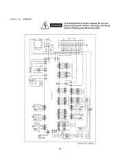
Electric Wiring Diagrams Outdoor Unit CLM1972 To avoid electrical shock hazard, be sure to WARNING disconnect power before checking, servicing and/or cleaning any electrical parts. 8FA2-5257-59400-1 42 COMPRESSOR THERMISTOR BLK BLK COMP COIL THERMISTOR YEL YEL BLK BLK OUTDOOR THERMISTOR AW THERMISTOR YEL YEL YEL YEL AN THERMISTOR ...
Electric Wiring Diagrams Outdoor Unit CLM1972 To avoid electrical shock hazard, be sure to WARNING disconnect power before checking, servicing and/or cleaning any electrical parts. 8FA2-5257-59400-1 42 COMPRESSOR THERMISTOR BLK BLK COMP COIL THERMISTOR YEL YEL BLK BLK OUTDOOR THERMISTOR AW THERMISTOR YEL YEL YEL YEL AN THERMISTOR ...
Service Manual
Page 43
Outdoor Unit CLM2472 8FA2-5257-59600-1 43 COMPRESSOR THERMISTOR BLK BLK COMP COIL THERMISTOR YEL YEL BLK BLK OUTDOOR THERMISTOR AW THERMISTOR YEL YEL YEL YEL AN THERMISTOR ... UNIT UNIT UNIT TO INDOOR UNIT To avoid electrical shock hazard, be sure to WARNING disconnect power before checking, servicing and/or cleaning any electrical parts.
Outdoor Unit CLM2472 8FA2-5257-59600-1 43 COMPRESSOR THERMISTOR BLK BLK COMP COIL THERMISTOR YEL YEL BLK BLK OUTDOOR THERMISTOR AW THERMISTOR YEL YEL YEL YEL AN THERMISTOR ... UNIT UNIT UNIT TO INDOOR UNIT To avoid electrical shock hazard, be sure to WARNING disconnect power before checking, servicing and/or cleaning any electrical parts.

Service Manual
Page 44
... UNIT UNIT UNIT TO INDOOR UNIT To avoid electrical shock hazard, be sure to WARNING disconnect power before checking, servicing and/or cleaning any electrical parts.
... UNIT UNIT UNIT TO INDOOR UNIT To avoid electrical shock hazard, be sure to WARNING disconnect power before checking, servicing and/or cleaning any electrical parts.
Service Manual
Page 51
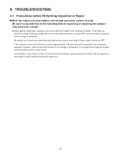
... Be sure to pay attention to dissipate. If the outdoor control circuit board is normal, approximately 180 seconds will be required to touch any electrified parts before Performing Inspection or Repair Both the indoor unit and outdoor unit include electronic control circuits. For example, if the outdoor control circuit board fuse...
... Be sure to pay attention to dissipate. If the outdoor control circuit board is normal, approximately 180 seconds will be required to touch any electrified parts before Performing Inspection or Repair Both the indoor unit and outdoor unit include electronic control circuits. For example, if the outdoor control circuit board fuse...
Service Manual
Page 54
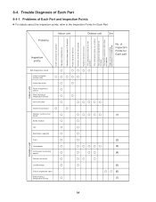
...does not operate. Does not cool or cooling performance is inadequate. Outdoor fan dose not turn . Trouble Diagnosis of Inspection Points for Each Part. Outdoor unit does not operate. Indoor fan dose not turn . The compressor stops on occasion. The electric expansion valve does not operate.... protective sensor (4) Outdoor fan motor Coil thermistor (5) Electric expansion valve (6) Branch tubing temperature sensor (7) Outdoor unit 54 8-4. Problems of Each Part and Inspection Points For details about the inspection points, refer to the Inspection Points for Each...
...does not operate. Does not cool or cooling performance is inadequate. Outdoor fan dose not turn . Trouble Diagnosis of Inspection Points for Each Part. Outdoor unit does not operate. Indoor fan dose not turn . The compressor stops on occasion. The electric expansion valve does not operate.... protective sensor (4) Outdoor fan motor Coil thermistor (5) Electric expansion valve (6) Branch tubing temperature sensor (7) Outdoor unit 54 8-4. Problems of Each Part and Inspection Points For details about the inspection points, refer to the Inspection Points for Each...
Service Manual
Page 55
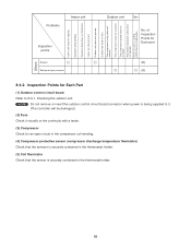
...to it. (The controller will be damaged.) (2) Fuse Check it visually or the continuity with a tester. (3) Compressor Check for Each Part (1) Outdoor control circuit board Refer to 8-3-1. Inspection Points for an open circuit in the compressor coil winding. (4) Compressor protective sensor (compressor ... is inadequate. The compressor (only) does not operate. The compressor speed does not increase. of Inspection Points for Each part (8) (9) 8-4-2. Operation lamp does not illuminate. Checking the outdoor unit. Others Indoor unit does not operate. Operation lamp blinking. Indoor...
...to it. (The controller will be damaged.) (2) Fuse Check it visually or the continuity with a tester. (3) Compressor Check for Each Part (1) Outdoor control circuit board Refer to 8-3-1. Inspection Points for an open circuit in the compressor coil winding. (4) Compressor protective sensor (compressor ... is inadequate. The compressor (only) does not operate. The compressor speed does not increase. of Inspection Points for Each part (8) (9) 8-4-2. Operation lamp does not illuminate. Checking the outdoor unit. Others Indoor unit does not operate. Operation lamp blinking. Indoor...
Service Manual
Page 56
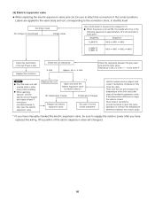
...are applied to the valve body and coil, corresponding to the connector colors, to 20 seconds for each point. Sequence CLM1972 MV0 MV1 MV2 CLM2472 CLM3172 MV0 MV1 MV2 MV3 Check the illumination of the red Power Lamp. Resistance is 46 + / - 4ohm at least 5 revolutions ...counterclockwise to fully open the valve. Model No. Then rotate 5 revolutions counterclockwise to measure the voltage (12 V). This part is closed. If the temperature difference is large, the valve is normal. Controller check No voltage on circuit board Voltage varies Use...
...are applied to the valve body and coil, corresponding to the connector colors, to 20 seconds for each point. Sequence CLM1972 MV0 MV1 MV2 CLM2472 CLM3172 MV0 MV1 MV2 MV3 Check the illumination of the red Power Lamp. Resistance is 46 + / - 4ohm at least 5 revolutions ...counterclockwise to fully open the valve. Model No. Then rotate 5 revolutions counterclockwise to measure the voltage (12 V). This part is closed. If the temperature difference is large, the valve is normal. Controller check No voltage on circuit board Voltage varies Use...

Service Manual
Page 68
...provide a solid, level foundation for a special problem, contact our sales/service outlet or your back. Carefully refer to check or repair electrical parts and wiring. • Keep your fingers. This prevents water damage and abnormal vibration. ...In an Area with High Winds Securely anchor the...water damage to walls and floors. ...In Moist or Uneven Locations Use a raised concrete pad or concrete blocks to reduce strain on the air conditioner can result in this document. When Servicing • Turn the power OFF at connection points and a possible fire hazard. Others CAUTION &#...
...provide a solid, level foundation for a special problem, contact our sales/service outlet or your back. Carefully refer to check or repair electrical parts and wiring. • Keep your fingers. This prevents water damage and abnormal vibration. ...In an Area with High Winds Securely anchor the...water damage to walls and floors. ...In Moist or Uneven Locations Use a raised concrete pad or concrete blocks to reduce strain on the air conditioner can result in this document. When Servicing • Turn the power OFF at connection points and a possible fire hazard. Others CAUTION &#...
Service Manual
Page 69
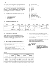
...for connecting the outdoor unit to purchase these materials separately from a local source, you will need: 1. Refer to install the air conditioning system. If the electric wiring diagram does not appear in kits which contain the narrow and wide tubing, fittings and ...insulation. Knife or wire stripper 4. Accessories Supplied with Unit Table 1 Parts Figure Q'ty Parts Hex wrench 1 Cushion rubber Labels for Installation (not supplied) 1. Core bits 9. Type of the insulation should be not less than 5/16...
...for connecting the outdoor unit to purchase these materials separately from a local source, you will need: 1. Refer to install the air conditioning system. If the electric wiring diagram does not appear in kits which contain the narrow and wide tubing, fittings and ...insulation. Knife or wire stripper 4. Accessories Supplied with Unit Table 1 Parts Figure Q'ty Parts Hex wrench 1 Cushion rubber Labels for Installation (not supplied) 1. Core bits 9. Type of the insulation should be not less than 5/16...

Service Manual
Page 77
... K 4- 1/4" G (4- 6.5 mm) AE G F B G Fig. 5g D Fig. 5h For Air Intake Dimensions A B C D E F G Model CLM1972, CLM2472 (inch) 25-3/16 25/32 1-31/32 25 10-5/8 10-5/8 25/64 (mm) 640 20 50 635 270 270 10 CLM3172 (inch) 25-3/16 25/32 1-3/8 30-29/32 13-25/32 13-25/32 25/64 (mm) 640 20 35 785 350 350 10...16 2-3/8 3-11/32 31/32 55 465 60 85 25 Material to be used: Metal plate with corrosion protection treatment Plate thickness: 0.0394 to 0.0472" (1.0 to 1.2 mm) (2) Parts required (field supply except for screws) Air Intake Baffle Item Q'ty Remarks Baffle plate 1 Screw 5/...
... K 4- 1/4" G (4- 6.5 mm) AE G F B G Fig. 5g D Fig. 5h For Air Intake Dimensions A B C D E F G Model CLM1972, CLM2472 (inch) 25-3/16 25/32 1-31/32 25 10-5/8 10-5/8 25/64 (mm) 640 20 50 635 270 270 10 CLM3172 (inch) 25-3/16 25/32 1-3/8 30-29/32 13-25/32 13-25/32 25/64 (mm) 640 20 35 785 350 350 10...16 2-3/8 3-11/32 31/32 55 465 60 85 25 Material to be used: Metal plate with corrosion protection treatment Plate thickness: 0.0394 to 0.0472" (1.0 to 1.2 mm) (2) Parts required (field supply except for screws) Air Intake Baffle Item Q'ty Remarks Baffle plate 1 Screw 5/...

Service Manual
Page 78
... the unit using field supply bolts and nuts. 4. G When the windbaffle is between 19/32 - 25/32 inch (15 - 20 mm). 5. Install the windbaffle on the unit, the unit has higher...chips do not drop into the unit. 12 Drilling of the bolts and heat exchanger and other parts inside the unit, install the windbaffle using the above screws. Remove the panel side L, and ... procedure 1. Put (sandwich) the windbaffle between 13/32 - 19/32 inch (10 - 15 mm). 4. Air Discharge Baffle 1. Use washers and spring washers to tightly fasten the windbaffle to the unit. These screws are 15...
... the unit using field supply bolts and nuts. 4. G When the windbaffle is between 19/32 - 25/32 inch (15 - 20 mm). 5. Install the windbaffle on the unit, the unit has higher...chips do not drop into the unit. 12 Drilling of the bolts and heat exchanger and other parts inside the unit, install the windbaffle using the above screws. Remove the panel side L, and ... procedure 1. Put (sandwich) the windbaffle between 13/32 - 19/32 inch (10 - 15 mm). 4. Air Discharge Baffle 1. Use washers and spring washers to tightly fasten the windbaffle to the unit. These screws are 15...

Service Manual
Page 84
...183;in (70 - 110 kgf·cm) (Tighten by using the gas inside the outdoor unit.) D Manifold gauge C (special for R410A) B Low-pressure High-pressure valve valve Vacuum pump A Leave the Lo Hi adapter (for R410A) Fig. 20 Vacuum pump CAUTION In order to use a wrench to... Use a hex wrench of refrigerant may lead to corrosion of parts in the refrigerant system have been properly connected and all wiring for air purging. Note that uses R410A, the screw diameter at this purpose. Air Purging Air and moisture remaining in the refrigerant system Service valve on narrow ...
...183;in (70 - 110 kgf·cm) (Tighten by using the gas inside the outdoor unit.) D Manifold gauge C (special for R410A) B Low-pressure High-pressure valve valve Vacuum pump A Leave the Lo Hi adapter (for R410A) Fig. 20 Vacuum pump CAUTION In order to use a wrench to... Use a hex wrench of refrigerant may lead to corrosion of parts in the refrigerant system have been properly connected and all wiring for air purging. Note that uses R410A, the screw diameter at this purpose. Air Purging Air and moisture remaining in the refrigerant system Service valve on narrow ...
Service Manual
Page 87
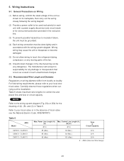
The manufacturer will accept no responsibility for any moving parts of local codes see the National Electric Code: ANSI/NFPA70. For field wiring requirements, please refer to insulation failure, the unit must be grounded. (4) Each ... the wiring system diagram (Fig. 25a or 25b) for control line and power line and fuse or circuit capacity. Table 6 Model AWG CM1972 / CLM1972 CM2472 / CLM2472 CM3172 / CLM3172 Max. Table 6 shows maximum wire lengths for the meaning of such unauthorized changes. 5-2. AWG (American Wire Gauge) 21 5. Power Line Length (ft.) Max...
The manufacturer will accept no responsibility for any moving parts of local codes see the National Electric Code: ANSI/NFPA70. For field wiring requirements, please refer to insulation failure, the unit must be grounded. (4) Each ... the wiring system diagram (Fig. 25a or 25b) for control line and power line and fuse or circuit capacity. Table 6 Model AWG CM1972 / CLM1972 CM2472 / CLM2472 CM3172 / CLM3172 Max. Table 6 shows maximum wire lengths for the meaning of such unauthorized changes. 5-2. AWG (American Wire Gauge) 21 5. Power Line Length (ft.) Max...

Service Manual
Page 88
... requirements. 3 indoor units with CM1972/CLM1972 4 indoor units with other grounds and do not have it shared with CM2472/CLM2472, CM3172/CLM3172 L1 Power supply L2 Single-phase 230/208VAC 60HZ Grounding line * Disconnect switch Field supply INDOOR UNIT Terminal ...risk of television, radio, stereo, telephone, security system, or intercom any moving part. Electrical noise may occur. G Grounding is necessary, especially for antenna, signal, or power lines of electric shock, each air conditioner unit must be allowed to touch refrigerant tubing, the compressor, or any closer ...
... requirements. 3 indoor units with CM1972/CLM1972 4 indoor units with other grounds and do not have it shared with CM2472/CLM2472, CM3172/CLM3172 L1 Power supply L2 Single-phase 230/208VAC 60HZ Grounding line * Disconnect switch Field supply INDOOR UNIT Terminal ...risk of television, radio, stereo, telephone, security system, or intercom any moving part. Electrical noise may occur. G Grounding is necessary, especially for antenna, signal, or power lines of electric shock, each air conditioner unit must be allowed to touch refrigerant tubing, the compressor, or any closer ...
