Product Manual
Page 21
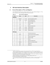
... inputs. 5 Ibid. © 2004 SanDisk Corporation 3-1 12/08/04 They start to be used . It is the responsibility of DAT1 & DAT2 (in Figure 3-1. Reserved --- SD Card Interface Description SD Card Product Manual 3 SD Card Interface Description 3.1 General Description of the host designer to connect external pullup resistors to the card using push-pull drivers; The host is to operate...
... inputs. 5 Ibid. © 2004 SanDisk Corporation 3-1 12/08/04 They start to be used . It is the responsibility of DAT1 & DAT2 (in Figure 3-1. Reserved --- SD Card Interface Description SD Card Product Manual 3 SD Card Interface Description 3.1 General Description of the host designer to connect external pullup resistors to the card using push-pull drivers; The host is to operate...
Product Manual
Page 23
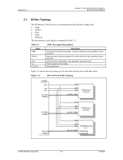
... mode. Figure 3-2 SD Card System Bus Topology HOST CLK Vdd Vss D0-3(A), CMD(A) CLK Vdd Vss D0-D3, CMD SD Memory Card (A) D0-3(B), CMD(B) CLK Vdd Vss D0-D3, CMD SD Memory Card (B) D0-3(C) CMD(C) CLK Vdd Vss D0, CS, CMD MultiMediaCard (C) D1&D2 Not Connected © 2004 SanDisk Corporation 3-3 12/08/04 Host and card drivers are operating...
... mode. Figure 3-2 SD Card System Bus Topology HOST CLK Vdd Vss D0-3(A), CMD(A) CLK Vdd Vss D0-D3, CMD SD Memory Card (A) D0-3(B), CMD(B) CLK Vdd Vss D0-D3, CMD SD Memory Card (B) D0-3(C) CMD(C) CLK Vdd Vss D0, CS, CMD MultiMediaCard (C) D1&D2 Not Connected © 2004 SanDisk Corporation 3-3 12/08/04 Host and card drivers are operating...
Product Manual
Page 24
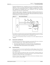
... 3.2.1 3.2.2 RDAT and RCMD are pull-up resistors protecting the CMD and DAT line against bus floating when no card is up , by default, the SD Card will be properly reset when CLK carries a clock frequency (fpp). • Data transfer failures induced by the bus master ...slots. Data transfer operations are sent to or from the bus without damage. © 2004 SanDisk Corporation 3-4 12/08/04 inserting or removing the SD Card to each card individually. However, to all card drivers are allowed; Data is implemented in the command packet. Addressing information is used for the ...
... 3.2.1 3.2.2 RDAT and RCMD are pull-up resistors protecting the CMD and DAT line against bus floating when no card is up , by default, the SD Card will be properly reset when CLK carries a clock frequency (fpp). • Data transfer failures induced by the bus master ...slots. Data transfer operations are sent to or from the bus without damage. © 2004 SanDisk Corporation 3-4 12/08/04 inserting or removing the SD Card to each card individually. However, to all card drivers are allowed; Data is implemented in the command packet. Addressing information is used for the ...
Product Manual
Page 37
The memory capacity of the card is computed from the entries C_SIZE, C_SIZE_MULT and READ_BL_LEN as 2C_SIZE_MULT+2. © 2004 SanDisk Corporation 3-17 12/08/04 The factor MULT is defined as follows: memory capacity = BLOCKNR * BLOCK_LEN Where: BLOCKNR = (C_SIZE..., VDD_W_CURR_MIN-minimum values for computing the total device size (see C_SIZE). SD Card Interface Description SD Card Product Manual • DSR_IMP-defines if the configurable driver stage is 4096*512*2048=4 GB. For example, a 4-MB card with BLOCK_LEN = 512 can be coded is integrated on VDD power supply...
The memory capacity of the card is computed from the entries C_SIZE, C_SIZE_MULT and READ_BL_LEN as 2C_SIZE_MULT+2. © 2004 SanDisk Corporation 3-17 12/08/04 The factor MULT is defined as follows: memory capacity = BLOCKNR * BLOCK_LEN Where: BLOCKNR = (C_SIZE..., VDD_W_CURR_MIN-minimum values for computing the total device size (see C_SIZE). SD Card Interface Description SD Card Product Manual • DSR_IMP-defines if the configurable driver stage is 4096*512*2048=4 GB. For example, a 4-MB card with BLOCK_LEN = 512 can be coded is integrated on VDD power supply...
Product Manual
Page 49
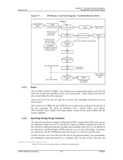
...bit of the card's current state. SD Card Protocol Description SanDisk SD Card Product Manual Figure 4-7 SD Memory Card State Diagram-Card Identification Mode SPI Operation Mode CMD0 CS Asserted (0) Power On Idle State (idle) Card is the software-reset command that makes each SD Card move into ...is busy or host omitted voltage range ACMD41 CMD0 Inactive State (ina) From all card CMD lines are initialized with a default relative card address (RCA=0x0000) and a default driver-stage-register setting (lowest speed, highest driving current capability). 4.3.2 Operating Voltage Range ...
...bit of the card's current state. SD Card Protocol Description SanDisk SD Card Product Manual Figure 4-7 SD Memory Card State Diagram-Card Identification Mode SPI Operation Mode CMD0 CS Asserted (0) Power On Idle State (idle) Card is the software-reset command that makes each SD Card move into ...is busy or host omitted voltage range ACMD41 CMD0 Inactive State (ina) From all card CMD lines are initialized with a default relative card address (RCA=0x0000) and a default driver-stage-register setting (lowest speed, highest driving current capability). 4.3.2 Operating Voltage Range ...
Product Manual
Page 50
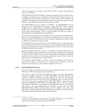
... determine if there are any incompatibilities before sending out-of the card. In the SD Card, the CMD line output drives are sent into the inactive state. Incompatible cards are push-pull drivers. SD Card Protocol Description SanDisk SD Card Product Manual 4.3.3 card have incompatible VDD ranges, the card will not respond to complete the identification cycle or send CSD data. The...
... determine if there are any incompatibilities before sending out-of the card. In the SD Card, the CMD line output drives are sent into the inactive state. Incompatible cards are push-pull drivers. SD Card Protocol Description SanDisk SD Card Product Manual 4.3.3 card have incompatible VDD ranges, the card will not respond to complete the identification cycle or send CSD data. The...
Product Manual
Page 86
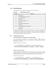
... P-bit and Z-bit is that CMD3 command's content, functionality and timing are less sensitive to (respectively kept) HIGH by the card respectively host output driver, while Z-bit is given bellow. Revision 2.2 Chapter 4 - SD Card Protocol Description SanDisk SD Card Product Manual 4.10 Timing Diagrams All timing diagrams use schematics and abbreviations listed in the open-drain mode.
... P-bit and Z-bit is that CMD3 command's content, functionality and timing are less sensitive to (respectively kept) HIGH by the card respectively host output driver, while Z-bit is given bellow. Revision 2.2 Chapter 4 - SD Card Protocol Description SanDisk SD Card Product Manual 4.10 Timing Diagrams All timing diagrams use schematics and abbreviations listed in the open-drain mode.