Product Manual
Page 4
Revision 2.2 SanDisk SD Card Product Manual 5.5 Data Write 5-3 5.6 Erase and Write Protect Management 5-4 5.7 Read CID/CSD Registers 5-5 5.8 Reset Sequence 5-5 5.9 Clock Control 5-5 5.10 Error Conditions 5-6 5.11 Memory Array Partitioning 5-7 5.12 Card Lock/Unlock 5-7 5.13 Application-specific Commands 5-7 5.14 Copyright Protection Commands 5-7 5.15 Switch Function Command 5-7 5.16 High-speed Mode (25MB/sec interface speed 5-7 5.17 SPI Command Set 5-8 5.18...
Revision 2.2 SanDisk SD Card Product Manual 5.5 Data Write 5-3 5.6 Erase and Write Protect Management 5-4 5.7 Read CID/CSD Registers 5-5 5.8 Reset Sequence 5-5 5.9 Clock Control 5-5 5.10 Error Conditions 5-6 5.11 Memory Array Partitioning 5-7 5.12 Card Lock/Unlock 5-7 5.13 Application-specific Commands 5-7 5.14 Copyright Protection Commands 5-7 5.15 Switch Function Command 5-7 5.16 High-speed Mode (25MB/sec interface speed 5-7 5.17 SPI Command Set 5-8 5.18...

Product Manual
Page 6
...mail: [email protected] URL: http://www.sdcard.org © 2004 SanDisk Corporation 1-2 12/08/04 Introduction SanDisk SD Card Product Manual 1.2 Features SanDisk SD Card features include: ►Up to 2-GB of data storage ►SD-protocol compatible ►Supports SPI mode ► Targeted for portable and stationary... Variable clock rate 0-25 MHz (default), 0-50MHz (high-speed) ►Data transfer rate Up to 50 MB/sec data transfer rate (using 4 parallel data lines) Maximum data rate with up to 10 cards ►Correction of memory-field errors ►Copyrights Protection mechanism...
...mail: [email protected] URL: http://www.sdcard.org © 2004 SanDisk Corporation 1-2 12/08/04 Introduction SanDisk SD Card Product Manual 1.2 Features SanDisk SD Card features include: ►Up to 2-GB of data storage ►SD-protocol compatible ►Supports SPI mode ► Targeted for portable and stationary... Variable clock rate 0-25 MHz (default), 0-50MHz (high-speed) ►Data transfer rate Up to 50 MB/sec data transfer rate (using 4 parallel data lines) Maximum data rate with up to 10 cards ►Correction of memory-field errors ►Copyrights Protection mechanism...

Product Manual
Page 30
... 7 --- ns Outputs CMD, DAT - SD Card Interface Description SD Card Product Manual Parameter Symbol Min Max Clock (...50 Unit Remark ns CL < 25 pF (1 card) ns CL < 25 pF (1 card) 3.4.7 Bus Timing (high-speed mode) High-speed mode dataIn/dataOut timing is illustrated in Table 3-8. ...speed) Table 3-8 Bus Timing Parameter Values (high-speed) Parameter Symbol Min Max Unit Clock (CLK) - Revision 2.2 Chapter 3 - VIL Output delay time during Data tOSU 0 14 Transfer mode Output delay time during Data tODLY --- 14 ns Transfer mode Remark © 2004 SanDisk...
... 7 --- ns Outputs CMD, DAT - SD Card Interface Description SD Card Product Manual Parameter Symbol Min Max Clock (...50 Unit Remark ns CL < 25 pF (1 card) ns CL < 25 pF (1 card) 3.4.7 Bus Timing (high-speed mode) High-speed mode dataIn/dataOut timing is illustrated in Table 3-8. ...speed) Table 3-8 Bus Timing Parameter Values (high-speed) Parameter Symbol Min Max Unit Clock (CLK) - Revision 2.2 Chapter 3 - VIL Output delay time during Data tOSU 0 14 Transfer mode Output delay time during Data tODLY --- 14 ns Transfer mode Remark © 2004 SanDisk...
Product Manual
Page 33
...and coded according to access the card data. Revision 2.2 Chapter 3 - SD Card Interface Description SD Card Product Manual 3.5.3 Card Specific Data Register The Card Specific Data (CSD) Register configuration...SPEED CCC 12 R READ_BL_ 4 R LEN READ_BL_ 1 R PARTIAL WRITE_BLK_ 1 R MISALIGN READ_BLK_ 1 R MISALIGN DSR_IMP 1 R --C_SIZE 2 R 12 R VDD_R_ 3 R CURR_MIN VDD_R_ 3 R CURR_MAX [111: 0 104] [103:96] Default 25MHz High-speed...Card command classes Max. In Table 3-11, the Cell Type column defines the CSD field as read current @VDD © 2004 SanDisk...
...and coded according to access the card data. Revision 2.2 Chapter 3 - SD Card Interface Description SD Card Product Manual 3.5.3 Card Specific Data Register The Card Specific Data (CSD) Register configuration...SPEED CCC 12 R READ_BL_ 4 R LEN READ_BL_ 1 R PARTIAL WRITE_BLK_ 1 R MISALIGN READ_BLK_ 1 R MISALIGN DSR_IMP 1 R --C_SIZE 2 R 12 R VDD_R_ 3 R CURR_MIN VDD_R_ 3 R CURR_MAX [111: 0 104] [103:96] Default 25MHz High-speed...Card command classes Max. In Table 3-11, the Cell Type column defines the CSD field as read current @VDD © 2004 SanDisk...

Product Manual
Page 34
...write current @VDD min. write data block length Partial blocks for MMC compatibility Write speed factor Ah 9h 0 00000b 0b Max. Device size multiplier Erase single block enable Erase...SanDisk Corporation 3-14 12/08/04 CSD Code Description 111b 110b 0x07 0x07 0x06 0x05 0x04 0x03 0x03 0x03 1b 0011111b 1111111b 1b 0b 0100b max. SD Card Interface Description SD Card... Product Manual Field Width Cell Type CSD Slice CSD Value VDD_W_ 3 R [55:53] 100 mA CURR_MIN VDD_W_ 3 R [52:50] 80 mA CURR_MAX C_SIZE_ 3 R [49:47] 2G=2048 MULT 1G=1024...
...write current @VDD min. write data block length Partial blocks for MMC compatibility Write speed factor Ah 9h 0 00000b 0b Max. Device size multiplier Erase single block enable Erase...SanDisk Corporation 3-14 12/08/04 CSD Code Description 111b 110b 0x07 0x07 0x06 0x05 0x04 0x03 0x03 0x03 1b 0011111b 1111111b 1b 0b 0100b max. SD Card Interface Description SD Card... Product Manual Field Width Cell Type CSD Slice CSD Value VDD_W_ 3 R [55:53] 100 mA CURR_MIN VDD_W_ 3 R [52:50] 80 mA CURR_MAX C_SIZE_ 3 R [49:47] 2G=2048 MULT 1G=1024...
Product Manual
Page 49
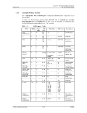
... bus communication. © 2004 SanDisk Corporation 4-5 12/08/04 SD Card Protocol Description SanDisk SD Card Product Manual Figure 4-7 SD Memory Card State Diagram-Card Identification Mode SPI Operation Mode CMD0 CS Asserted (0) Power On Idle State (idle) Card is busy or host omitted voltage...input mode, waiting for VDD are expected to establish communication with a default relative card address (RCA=0x0000) and a default driver-stage-register setting (lowest speed, highest driving current capability). 4.3.2 Operating Voltage Range Validation The physical specification standard...
... bus communication. © 2004 SanDisk Corporation 4-5 12/08/04 SD Card Protocol Description SanDisk SD Card Product Manual Figure 4-7 SD Memory Card State Diagram-Card Identification Mode SPI Operation Mode CMD0 CS Asserted (0) Power On Idle State (idle) Card is busy or host omitted voltage...input mode, waiting for VDD are expected to establish communication with a default relative card address (RCA=0x0000) and a default driver-stage-register setting (lowest speed, highest driving current capability). 4.3.2 Operating Voltage Range Validation The physical specification standard...
Product Manual
Page 63
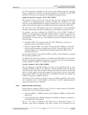
... after APP_CMD command, it the card will have the APP_CMD bit set, indicating that are two function groups defined. • Card Access Mode: 12.5MB/sec interface speed (default) or 25MB/sec interface speed (high-speed) • Card Command System: Standard Command set ... Function command (CMD6) is used . The card will be selected ('tran_state') before sending CMD56. Currently there are compatible with CMD16. SD Card Protocol Description SanDisk SD Card Product Manual 4.4.9 new SD card-specific commands, the SD Card uses the application-specific commands feature to the host...
... after APP_CMD command, it the card will have the APP_CMD bit set, indicating that are two function groups defined. • Card Access Mode: 12.5MB/sec interface speed (default) or 25MB/sec interface speed (high-speed) • Card Command System: Standard Command set ... Function command (CMD6) is used . The card will be selected ('tran_state') before sending CMD56. Currently there are compatible with CMD16. SD Card Protocol Description SanDisk SD Card Product Manual 4.4.9 new SD card-specific commands, the SD Card uses the application-specific commands feature to the host...
Product Manual
Page 66
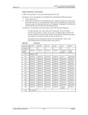
... Reserved Reserved Reserved Reserved Vendor specific High-speed Reserved Reserved Reserved Reserved Reserved Reserved Reserved Reserved Reserved Reserved Reserved Reserved Reserved © 2004 SanDisk Corporation 4-22 12/08/04 Slice Group No. Revision 2.2 Chapter 4 - Set the mode bit to 0x0 selects the default function. SD Card Protocol Description SanDisk SD Card Product Manual Mode 1 Operation-Set Function...
... Reserved Reserved Reserved Reserved Vendor specific High-speed Reserved Reserved Reserved Reserved Reserved Reserved Reserved Reserved Reserved Reserved Reserved Reserved Reserved © 2004 SanDisk Corporation 4-22 12/08/04 Slice Group No. Revision 2.2 Chapter 4 - Set the mode bit to 0x0 selects the default function. SD Card Protocol Description SanDisk SD Card Product Manual Mode 1 Operation-Set Function...
Product Manual
Page 69
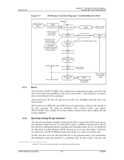
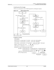
Figure 4-12 Switch Function Flow Start Spec 1.0-1.10 Card version no.? Spec 1.10 or higher func SD Card Protocol Description SanDisk SD Card Product Manual Switch Function Flow Example The host is recommended to take the following flow for switching the function. Revision 2.2 Chapter 4 -
Figure 4-12 Switch Function Flow Start Spec 1.0-1.10 Card version no.? Spec 1.10 or higher func SD Card Protocol Description SanDisk SD Card Product Manual Switch Function Flow Example The host is recommended to take the following flow for switching the function. Revision 2.2 Chapter 4 -

Product Manual
Page 70
... 0000 1111 0001 0000' [375:0] = Reserved (All 0s) 4.4.11 Error High-speed Mode19 (25MB/sec interface speed) Although revision 1.01 of growing memory size. Revision 1.10 (and greater) SD cards can be placed in Default Speed mode. Check function with no error CMD6 argument = '1000 0000 1111 1111 1111 ... 0000 0000 0000 0000 0001' [375:0] = Reserved (All 0s) For eC High-speed Case (4) - To achieve the 25MB/sec interface speed, the clock rate is not supported in SPI Mode. © 2004 SanDisk Corporation 4-26 12/08/04 Switch function with error CMD6 argument = '0000 0000 1111...
... 0000 1111 0001 0000' [375:0] = Reserved (All 0s) 4.4.11 Error High-speed Mode19 (25MB/sec interface speed) Although revision 1.01 of growing memory size. Revision 1.10 (and greater) SD cards can be placed in Default Speed mode. Check function with no error CMD6 argument = '1000 0000 1111 1111 1111 ... 0000 0000 0000 0000 0001' [375:0] = Reserved (All 0s) For eC High-speed Case (4) - To achieve the 25MB/sec interface speed, the clock rate is not supported in SPI Mode. © 2004 SanDisk Corporation 4-26 12/08/04 Switch function with error CMD6 argument = '0000 0000 1111...

Product Manual
Page 71
... flow. Also, in High-speed Mode, the TRAN_SPEED value in frequency range of the following procedures will be changed at less than 50-msec intervals. © 2004 SanDisk Corporation 4-27 12/08/04 SD Card Protocol Description SanDisk SD Card Product Manual The host drives ...only one between the various functions of the command-system function group, will change for SD command system expansion via the switch command...
... flow. Also, in High-speed Mode, the TRAN_SPEED value in frequency range of the following procedures will be changed at less than 50-msec intervals. © 2004 SanDisk Corporation 4-27 12/08/04 SD Card Protocol Description SanDisk SD Card Product Manual The host drives ...only one between the various functions of the command-system function group, will change for SD command system expansion via the switch command...
Product Manual
Page 97
.... SPI Protocol SD Card Product Manual recover (e.g., reset the card, power cycle, reject). Write The R2W_FACTOR field in the following sections. After the busy signal clears, the host should obtain the result of the CMD0 command R1 response. 5.16 High-speed Mode (25MB/sec interface speed) Not available ... Array Partitioning See SD Card Bus Mode. 5.12 Card Lock/Unlock Usage of the data block. These card parameters define the typical delay between the end bit of the read command and the start bit of card lock and unlock commands in SPI Mode. © 2004 SanDisk Corporation 5-7 12/...
.... SPI Protocol SD Card Product Manual recover (e.g., reset the card, power cycle, reject). Write The R2W_FACTOR field in the following sections. After the busy signal clears, the host should obtain the result of the CMD0 command R1 response. 5.16 High-speed Mode (25MB/sec interface speed) Not available ... Array Partitioning See SD Card Bus Mode. 5.12 Card Lock/Unlock Usage of the data block. These card parameters define the typical delay between the end bit of the read command and the start bit of card lock and unlock commands in SPI Mode. © 2004 SanDisk Corporation 5-7 12/...
Product Manual
Page 119
...the maximum specification. © 2002 SanDisk Corporation 3 9/30/02, Lit# 80-11-00160 the MultiMediaCard powers up in their design, the clock speed should be incorrect or invalid. Refer to the card may be controllable by MultiMediaCard and SD Card Associations. Although these options and provide ...setup, hold, and other options. Timing specifications Design engineers must ensure that integrate the MultiMediaCard and/or SD Card. These can run at the maximum clock speed. Timing There are important timing issues for read access and program time are also very critical to ...
...the maximum specification. © 2002 SanDisk Corporation 3 9/30/02, Lit# 80-11-00160 the MultiMediaCard powers up in their design, the clock speed should be incorrect or invalid. Refer to the card may be controllable by MultiMediaCard and SD Card Associations. Although these options and provide ...setup, hold, and other options. Timing specifications Design engineers must ensure that integrate the MultiMediaCard and/or SD Card. These can run at the maximum clock speed. Timing There are important timing issues for read access and program time are also very critical to ...

Product Manual
Page 120
... with all MultiMediaCards and SD cards regardless of 100 clocks. Both cards support the 1-bit SPI bus that has CLK, CMD, and DAT bus pins. The CMD and DAT pins are bi-directional on the clock speed and bus mode. The SD Card also supports a 4-bit and a 1-bit SD bi-directional bus mode.... The TAAC factor's unit is the data transfer rate between the card's buffer and host. © 2002 SanDisk Corporation 4 9/30/02, Lit# 80-11-00160 The...
... with all MultiMediaCards and SD cards regardless of 100 clocks. Both cards support the 1-bit SPI bus that has CLK, CMD, and DAT bus pins. The CMD and DAT pins are bi-directional on the clock speed and bus mode. The SD Card also supports a 4-bit and a 1-bit SD bi-directional bus mode.... The TAAC factor's unit is the data transfer rate between the card's buffer and host. © 2002 SanDisk Corporation 4 9/30/02, Lit# 80-11-00160 The...

Product Manual
Page 121
... Flash RAM, and busy time to read busy time to the card's buffer. MultiMediaCard and SD Card Clock Speed and Burst Rate Product MultiMediaCard SPI Bus mode MMC 1-bit mode SD Card SPI Bus mode SD 1-bit mode SD 4-bit mode Maximum Clock Speed and Burst Rate Clock Speed Burst Rate 20 MHz 2.5 MB/s 20 MHz 2.5 MB/s 25 ...to move 512 bytes Clock Speed Time 20 MHz 204.8 us 20 MHz 204.8 us 25 MHz 25 MHz 25 MHz 163.8 us 163.8 us 41 us © 2002 SanDisk Corporation 5 9/30/02, Lit# 80-11-00160 or 4-bit bus mode can have a 4x speed effect on the time spent servicing the SD Card.
... Flash RAM, and busy time to read busy time to the card's buffer. MultiMediaCard and SD Card Clock Speed and Burst Rate Product MultiMediaCard SPI Bus mode MMC 1-bit mode SD Card SPI Bus mode SD 1-bit mode SD 4-bit mode Maximum Clock Speed and Burst Rate Clock Speed Burst Rate 20 MHz 2.5 MB/s 20 MHz 2.5 MB/s 25 ...to move 512 bytes Clock Speed Time 20 MHz 204.8 us 20 MHz 204.8 us 25 MHz 25 MHz 25 MHz 163.8 us 163.8 us 41 us © 2002 SanDisk Corporation 5 9/30/02, Lit# 80-11-00160 or 4-bit bus mode can have a 4x speed effect on the time spent servicing the SD Card.

Product Manual
Page 122
.... Singleblock mode reads and writes data one block buffer gets full during card insertion. The card does not enter a busy state until the write process is complete. If speed is critical in to the card's maximum. © 2002 SanDisk Corporation 6 9/30/02, Lit# 80-11-00160 Therefore when planning ...the ability to turn power to have software power control of the design. However, if speed is not critical-for example, a data-logger design that should be implemented in a MultiMediaCard or SD Card design. When the initialization process is complete, the host can cycle the power and start...
.... Singleblock mode reads and writes data one block buffer gets full during card insertion. The card does not enter a busy state until the write process is complete. If speed is critical in to the card's maximum. © 2002 SanDisk Corporation 6 9/30/02, Lit# 80-11-00160 Therefore when planning ...the ability to turn power to have software power control of the design. However, if speed is not critical-for example, a data-logger design that should be implemented in a MultiMediaCard or SD Card design. When the initialization process is complete, the host can cycle the power and start...
