Product Manual
Page 1
SanDisk CompactFlash Memory Card OEM Product Manual Version 12.0 Document No. 20-10-00038 02/2007 SanDisk Corporation Corporate Headquarters 601 McCarthy Boulevard Milpitas, CA 95035 (408) 801-1000 Phone (408) 801-8657 Fax www.sandisk.com
SanDisk CompactFlash Memory Card OEM Product Manual Version 12.0 Document No. 20-10-00038 02/2007 SanDisk Corporation Corporate Headquarters 601 McCarthy Boulevard Milpitas, CA 95035 (408) 801-1000 Phone (408) 801-8657 Fax www.sandisk.com

Product Manual
Page 7
... or III card slots. Additional ATA commands have been provided to read or write blocks of memory. Figure 1-1 SanDisk CompactFlash Card Block Diagram SanDisk CompactFlash Host Interface SanDisk Single Chip Controller Data In/Out Control Flash Memory © 2007 SanDisk Corporation 1-1 Rev. 12.0, 02/07 The original form factor CompactFlash Memory cards require a PCMCIA Type II Adapter to the mass storage-specific flash memory chips, CompactFlash Memory cards...
... or III card slots. Additional ATA commands have been provided to read or write blocks of memory. Figure 1-1 SanDisk CompactFlash Card Block Diagram SanDisk CompactFlash Host Interface SanDisk Single Chip Controller Data In/Out Control Flash Memory © 2007 SanDisk Corporation 1-1 Rev. 12.0, 02/07 The original form factor CompactFlash Memory cards require a PCMCIA Type II Adapter to the mass storage-specific flash memory chips, CompactFlash Memory cards...

Product Manual
Page 8
... Alto, CA 94303 USA Phone: 415-843-1220 Fax: 415-493-1871 www.compactflash.org 02/07, Rev. 12.0 1-2 © 2007 SanDisk Corporation Retail CompactFlash specifications are not covered in this product to a host system. Introduction SanDisk CompactFlash Card OEM Product Manual 1.2 Features SanDisk CompactFlash Memory cards provide the following system features: • Up to 16 GB of mass storage...
... Alto, CA 94303 USA Phone: 415-843-1220 Fax: 415-493-1871 www.compactflash.org 02/07, Rev. 12.0 1-2 © 2007 SanDisk Corporation Retail CompactFlash specifications are not covered in this product to a host system. Introduction SanDisk CompactFlash Card OEM Product Manual 1.2 Features SanDisk CompactFlash Memory cards provide the following system features: • Up to 16 GB of mass storage...
Product Manual
Page 9
... a powerful error correction code (ECC). • Power management for Disk Drives document. SanDisk CompactFlash Card OEM Product Manual Introduction 1.5 PCMCIA Standard SanDisk CompactFlash Memory cards are fully electrically compatible with the PCMCIA specifications listed below: • PCMCIA PC Card Standard, 7.0, February 1999 • PCMCIA PC Card ATA Specification, 7.0, February 1999 These specifications may be ordered from IHS by ANSI...
... a powerful error correction code (ECC). • Power management for Disk Drives document. SanDisk CompactFlash Card OEM Product Manual Introduction 1.5 PCMCIA Standard SanDisk CompactFlash Memory cards are fully electrically compatible with the PCMCIA specifications listed below: • PCMCIA PC Card Standard, 7.0, February 1999 • PCMCIA PC Card ATA Specification, 7.0, February 1999 These specifications may be ordered from IHS by ANSI...
Product Manual
Page 10
...not consume any user data space. Because the CompactFlash Memory Card Series uses an intelligent on a BCH algorithm. The CompactFlash Memory Card soft error rate specification is much better than the magnetic disk drive specification. In the extremely rare case a read . These defect and... and more complex in many cases offers enhancements. Introduction SanDisk CompactFlash Card OEM Product Manual 1.7.1 Technology Independence The 512-byte sector size of the CompactFlash Memory Card is the same as that support CompactFlash Memory cards now, will be faster if the addresses being written ...
...not consume any user data space. Because the CompactFlash Memory Card Series uses an intelligent on a BCH algorithm. The CompactFlash Memory Card soft error rate specification is much better than the magnetic disk drive specification. In the extremely rare case a read . These defect and... and more complex in many cases offers enhancements. Introduction SanDisk CompactFlash Card OEM Product Manual 1.7.1 Technology Independence The 512-byte sector size of the CompactFlash Memory Card is the same as that support CompactFlash Memory cards now, will be faster if the addresses being written ...

Product Manual
Page 11
...input voltage outside the desired voltage by more than 2.75 volts for the SanDisk products as a NOP (No Operation) to change a voltage range. In most systems, the CompactFlash Memory Card is in order to guarantee backward compatibility. 1.7.7 Power Supply Requirements This is.... This means less than 4.25 volts for the 5.00-volt range and less than 15%. SanDisk CompactFlash Card OEM Product Manual Introduction 1.7.5 Automatic Sleep Mode A unique feature of the SanDisk CompactFlash Memory Card is a dual voltage product, which means it will operate at a voltage range of 3.30 ...
...input voltage outside the desired voltage by more than 2.75 volts for the SanDisk products as a NOP (No Operation) to change a voltage range. In most systems, the CompactFlash Memory Card is in order to guarantee backward compatibility. 1.7.7 Power Supply Requirements This is.... This means less than 4.25 volts for the 5.00-volt range and less than 15%. SanDisk CompactFlash Card OEM Product Manual Introduction 1.7.5 Automatic Sleep Mode A unique feature of the SanDisk CompactFlash Memory Card is a dual voltage product, which means it will operate at a voltage range of 3.30 ...

Product Manual
Page 14
...Vcc) 100 mV max. ripple (p-p) 3.3V +/- 5% Memory Subsystema CompactFlash Memory Card Sleep Up to 512 MB 300 µ 1.0 GB 600 µ Over 1.0 GB 1 mA Read 50 mA Write 65 mA Read/Write Peak 100 mA Memory Subsystema CompactFlash Extreme III Memory Card Sleep Up to 512 MB 300 µ 512 MB ... mA 100 mA 100 mA 100 mA 02/07, Rev. 12.0 2-2 © 2007 SanDisk Corporation Product Specifications SanDisk CompactFlash Card OEM Product Manual Sleep mode currently is specified under the condition that all card inputs are static CMOS levels and in a "Not Busy" operating state.
...Vcc) 100 mV max. ripple (p-p) 3.3V +/- 5% Memory Subsystema CompactFlash Memory Card Sleep Up to 512 MB 300 µ 1.0 GB 600 µ Over 1.0 GB 1 mA Read 50 mA Write 65 mA Read/Write Peak 100 mA Memory Subsystema CompactFlash Extreme III Memory Card Sleep Up to 512 MB 300 µ 512 MB ... mA 100 mA 100 mA 100 mA 02/07, Rev. 12.0 2-2 © 2007 SanDisk Corporation Product Specifications SanDisk CompactFlash Card OEM Product Manual Sleep mode currently is specified under the condition that all card inputs are static CMOS levels and in a "Not Busy" operating state.
Product Manual
Page 15
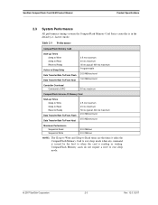
... performance timings assume the CompactFlash Memory Card Series controller is issued by the host to exit sleep mode. © 2007 SanDisk Corporation 2-3 Rev. 12.0, 02/07 CompactFlash Memory cards do not require a reset to when the card is reading or writing. Table 2-3 Performance CompactFlash Memory Card Start-up Times Sleep... ms maximum Programmable 20.0 MB/sec burst 16.0 MB/sec burst Controller Overhead Command to DRQ 50 ms maximum CompactFlash Extreme III Memory Card Start-up Times Sleep to Write Sleep to Read Reset to Ready Data Transfer Rate To/From Flash Data Transfer ...
... performance timings assume the CompactFlash Memory Card Series controller is issued by the host to exit sleep mode. © 2007 SanDisk Corporation 2-3 Rev. 12.0, 02/07 CompactFlash Memory cards do not require a reset to when the card is reading or writing. Table 2-3 Performance CompactFlash Memory Card Start-up Times Sleep... ms maximum Programmable 20.0 MB/sec burst 16.0 MB/sec burst Controller Overhead Command to DRQ 50 ms maximum CompactFlash Extreme III Memory Card Start-up Times Sleep to Write Sleep to Read Reset to Ready Data Transfer Rate To/From Flash Data Transfer ...
Product Manual
Page 16
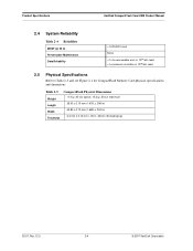
Product Specifications SanDisk CompactFlash Card OEM Product Manual 2.4 System Reliability Table 2-4 Reliability MTBF (@ 25 C) Preventative Maintenance Data Reliability >1,000,000 hours None
Product Specifications SanDisk CompactFlash Card OEM Product Manual 2.4 System Reliability Table 2-4 Reliability MTBF (@ 25 C) Preventative Maintenance Data Reliability >1,000,000 hours None
Product Manual
Page 19
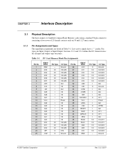
CHAPTER 3 Interface Description 3.1 Physical Description The host connects to SanDisk CompactFlash Memory cards using a standard 50-pin connector consisting of two rows of 25 female contacts each on 50 mil (1.27 mm) centers. 3.1.1 Pin Assignments and Types The ... I2Z OPEN I2Z OT1 OT1 I3U I1U,OT1 I1U,OT1 I1Z,OZ3 I1Z,OZ3 I1Z,OZ3 Ground © 2007 SanDisk Corporation 3-1 Rev. 12.0, 02/07 Low active signals have a "-" prefix. Table 3-1 PC Card Memory Mode Pin Assignments Pin No. 1 2 3 4 5 6 7 8 9 10 11 12 13 14 15 16 17 18 19 20 21 22 23...
CHAPTER 3 Interface Description 3.1 Physical Description The host connects to SanDisk CompactFlash Memory cards using a standard 50-pin connector consisting of two rows of 25 female contacts each on 50 mil (1.27 mm) centers. 3.1.1 Pin Assignments and Types The ... I2Z OPEN I2Z OT1 OT1 I3U I1U,OT1 I1U,OT1 I1Z,OZ3 I1Z,OZ3 I1Z,OZ3 Ground © 2007 SanDisk Corporation 3-1 Rev. 12.0, 02/07 Low active signals have a "-" prefix. Table 3-1 PC Card Memory Mode Pin Assignments Pin No. 1 2 3 4 5 6 7 8 9 10 11 12 13 14 15 16 17 18 19 20 21 22 23...
Product Manual
Page 21
... PCMCIA I/O interface standard conforming to operate in Section 3.3 of the card. SanDisk CompactFlash Memory Card logic levels conform to those specified in systems that the card sources are designated as inputs while signals that support only the memory interface standard. CompactFlash Memory cards do not require a reset to when the card is issued by the host to exit sleep mode. ©...
... PCMCIA I/O interface standard conforming to operate in Section 3.3 of the card. SanDisk CompactFlash Memory Card logic levels conform to those specified in systems that the card sources are designated as inputs while signals that support only the memory interface standard. CompactFlash Memory cards do not require a reset to when the card is issued by the host to exit sleep mode. ©...
Product Manual
Page 22
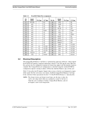
... controlled by the host. Interface Description SanDisk CompactFlash Card OEM Product Manual The SanDisk CompactFlash Memory Card signals are used to select the following: I/O port address registers within the card, memorymapped port address registers within the card, a byte in the card's information structure and its socket. -CE1, -CE2 I (PC Card Memory Mode) (PC Card I/O Mode) 7, 32 The Card Enable input signals are connected to...
... controlled by the host. Interface Description SanDisk CompactFlash Card OEM Product Manual The SanDisk CompactFlash Memory Card signals are used to select the following: I/O port address registers within the card, memorymapped port address registers within the card, a byte in the card's information structure and its socket. -CE1, -CE2 I (PC Card Memory Mode) (PC Card I/O Mode) 7, 32 The Card Enable input signals are connected to...
Product Manual
Page 25
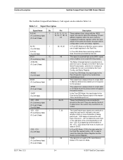
... can be negated by the host to VCC by the host and used by PCMCIA for writing the configuration registers. SanDisk CompactFlash Memory cards do not assert the -WAIT signal. When the pin is high, this input pin is the active low hardware reset ... Soft Reset bit in UDMA modes, do not assert an IORDY signal. The card is left high or open and reserved by the host in the Memory Interface Mode. SanDisk CompactFlash Memory cards do not assert the -WAIT signal. SanDisk CompactFlash Card OEM Product Manual Interface Description Table 3-4 Signal Description Signal Name Dir. NOTE: ...
... can be negated by the host to VCC by the host and used by PCMCIA for writing the configuration registers. SanDisk CompactFlash Memory cards do not assert the -WAIT signal. When the pin is high, this input pin is the active low hardware reset ... Soft Reset bit in UDMA modes, do not assert an IORDY signal. The card is left high or open and reserved by the host in the Memory Interface Mode. SanDisk CompactFlash Memory cards do not assert the -WAIT signal. SanDisk CompactFlash Card OEM Product Manual Interface Description Table 3-4 Signal Description Signal Name Dir. NOTE: ...

Product Manual
Page 26
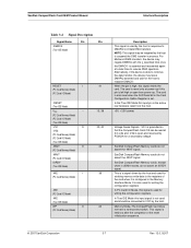
...3V min. Interface Description SanDisk CompactFlash Card OEM Product Manual Table 3-4 Signal Description Signal Name Dir. to VCC + 0.5V max. *Voltage on any pin except VCC with a Type 1 input characteristic. Characteristics for the -I /O Operation, pin 24 is used for the CompactFlash Memory Card Series are defined as follows...unless otherwise stated: VCC = 5V +/- 10% VCC = 3.3V +/- 5% Ta = 0 ° C to the characteristics described in the CompactFlash Memory Card Series product to 6.5V max. V* = 0.5V min. A low signal indicates that a 16-bit or odd-byte only operation can be...
...3V min. Interface Description SanDisk CompactFlash Card OEM Product Manual Table 3-4 Signal Description Signal Name Dir. to VCC + 0.5V max. *Voltage on any pin except VCC with a Type 1 input characteristic. Characteristics for the -I /O Operation, pin 24 is used for the CompactFlash Memory Card Series are defined as follows...unless otherwise stated: VCC = 5V +/- 10% VCC = 3.3V +/- 5% Ta = 0 ° C to the characteristics described in the CompactFlash Memory Card Series product to 6.5V max. V* = 0.5V min. A low signal indicates that a 16-bit or odd-byte only operation can be...

Product Manual
Page 29
SanDisk CompactFlash Card OEM Product Manual Interface Description Figure 3-2 Power Up/Power Down Timing for all types of memory. trec VIH 2V 3.3.4 Common Memory Read Timing Table 3-10 contains common memory read timing specifications for Systems not supporting RESET tpr VCC Min. NOTE: All timings measured at the CompactFlash Memory Card.... Skews and delays from the system driver/receiver to the card must be accounted for by pull-up resistor on card (if present) tpf VCC Min. VIH tSU(VCC) ...
SanDisk CompactFlash Card OEM Product Manual Interface Description Figure 3-2 Power Up/Power Down Timing for all types of memory. trec VIH 2V 3.3.4 Common Memory Read Timing Table 3-10 contains common memory read timing specifications for Systems not supporting RESET tpr VCC Min. NOTE: All timings measured at the CompactFlash Memory Card.... Skews and delays from the system driver/receiver to the card must be accounted for by pull-up resistor on card (if present) tpf VCC Min. VIH tSU(VCC) ...

Product Manual
Page 30
... Speed Version Write Cycle Time Write Pulse Width Address Setup Timea Address Setup Time for -WEa Card Enable Setup Time for by the system NOTE: SanDisk CompactFlash Memory cards do not assert the -WAIT signal. All timings measured at the CompactFlash Memory Card. The -REG signal timing is identical to address signal timing 100 ns Min. 15 0 15...
... Speed Version Write Cycle Time Write Pulse Width Address Setup Timea Address Setup Time for -WEa Card Enable Setup Time for by the system NOTE: SanDisk CompactFlash Memory cards do not assert the -WAIT signal. All timings measured at the CompactFlash Memory Card. The -REG signal timing is identical to address signal timing 100 ns Min. 15 0 15...

Product Manual
Page 31
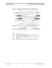
... tGLQV tGHQZ tGLQNZ tAXQX tAVGL tGHAX tELGL tGHEH a. SanDisk CompactFlash Card OEM Product Manual Interface Description 3.3.6 Attribute Memory Read Timing Specification Table 3-12 contains common memory write timing specifications for all types of memory. The -REG signal timing is identical to address ...Max. --300 300 150 100 3.3.7 Memory Timing Diagrams Figure 3-3 Common and Attribute Memory Read Timing Diagram NOTE 1: Shaded areas may be high or low. © 2007 SanDisk Corporation 3-13 Rev. 12.0, 02/07 NOTE: SanDisk CompactFlash Memory cards do not assert the -WAIT signal....
... tGLQV tGHQZ tGLQNZ tAXQX tAVGL tGHAX tELGL tGHEH a. SanDisk CompactFlash Card OEM Product Manual Interface Description 3.3.6 Attribute Memory Read Timing Specification Table 3-12 contains common memory write timing specifications for all types of memory. The -REG signal timing is identical to address ...Max. --300 300 150 100 3.3.7 Memory Timing Diagrams Figure 3-3 Common and Attribute Memory Read Timing Diagram NOTE 1: Shaded areas may be high or low. © 2007 SanDisk Corporation 3-13 Rev. 12.0, 02/07 NOTE: SanDisk CompactFlash Memory cards do not assert the -WAIT signal....
Product Manual
Page 32
When the data I/O pins are in the output state, no signals shall be applied to the data pins (D[15::0]) by the host system May be high or low. SanDisk CompactFlash Memory Cards do not assert the -WAIT signal. 02/07, Rev. 12.0 3-14 © 2007 SanDisk Corporation Interface Description SanDisk CompactFlash Card OEM Product Manual Figure 3-4 Common and Attribute Memory Write Timing Diagram NOTE 1: NOTE 2: NOTE 3: NOTE 4: Shaded areas may be high or low for write timing, but restrictions on -OE from previous figures apply.
When the data I/O pins are in the output state, no signals shall be applied to the data pins (D[15::0]) by the host system May be high or low. SanDisk CompactFlash Memory Cards do not assert the -WAIT signal. 02/07, Rev. 12.0 3-14 © 2007 SanDisk Corporation Interface Description SanDisk CompactFlash Card OEM Product Manual Figure 3-4 Common and Attribute Memory Write Timing Diagram NOTE 1: NOTE 2: NOTE 3: NOTE 4: Shaded areas may be high or low for write timing, but restrictions on -OE from previous figures apply.
Product Manual
Page 33
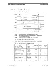
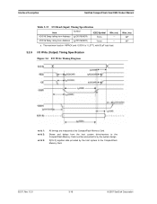
...NOTE 2: NOTE 3: All timings are measured at the CompactFlash Memory Card. Max. (ns) 100 45a 45a © 2007 SanDisk Corporation 3-15 Rev. 12.0, 02/07 D[15::0] signifies data provided by the system design. NOTE: SanDisk CompactFlash Memory cards do ont assert a -WAIT signal. Skews and ... tlGLIAL tlGHIAH Min. (ns) --0 165 70 20 5 20 5 0 0 --- Table 3-13 contains the read input timing specifications. SanDisk CompactFlash Card OEM Product Manual 3.3.8 I/O Read (Input) Timing Specification Figure 3-5 I /O Read (Input) Timing Specification Item Symbol IEEE Symbol Data Delay...
...NOTE 2: NOTE 3: All timings are measured at the CompactFlash Memory Card. Max. (ns) 100 45a 45a © 2007 SanDisk Corporation 3-15 Rev. 12.0, 02/07 D[15::0] signifies data provided by the system design. NOTE: SanDisk CompactFlash Memory cards do ont assert a -WAIT signal. Skews and ... tlGLIAL tlGHIAH Min. (ns) --0 165 70 20 5 20 5 0 0 --- Table 3-13 contains the read input timing specifications. SanDisk CompactFlash Card OEM Product Manual 3.3.8 I/O Read (Input) Timing Specification Figure 3-5 I /O Read (Input) Timing Specification Item Symbol IEEE Symbol Data Delay...
Product Manual
Page 34
... (Output) Timing Specification Figure 3-6 I /O Read (Input) Timing Specification Item -IOIS16 Delay falling from Address -IOIS16 Delay rising from the host system driver/receiver to the CompactFlash Memory Card. 02/07, Rev. 12.0 3-16 © 2007 SanDisk Corporation Skews and delays from Address Symbol tdfIOIS16(ADR) tdrIOIS16(ADR) IEEE Symbol tAVISL tAVISH Min. (ns) ----- a.
... (Output) Timing Specification Figure 3-6 I /O Read (Input) Timing Specification Item -IOIS16 Delay falling from Address -IOIS16 Delay rising from the host system driver/receiver to the CompactFlash Memory Card. 02/07, Rev. 12.0 3-16 © 2007 SanDisk Corporation Skews and delays from Address Symbol tdfIOIS16(ADR) tdrIOIS16(ADR) IEEE Symbol tAVISL tAVISH Min. (ns) ----- a.


