Product Manual
Page 3
....0 Description Merged CFlash 11.2 manual with CF ExtremeIII v1.2 to comply with CFA Spec v4.0. © 2007 SanDisk Corporation i Rev. 12.0, 02/07 registered trademark of SanDisk Corporation. updated to create v12.0; SanDisk CompactFlash Card OEM Product Manual SanDisk® Corporation general policy does not recommend the use of its products in life support applications where...
....0 Description Merged CFlash 11.2 manual with CF ExtremeIII v1.2 to comply with CFA Spec v4.0. © 2007 SanDisk Corporation i Rev. 12.0, 02/07 registered trademark of SanDisk Corporation. updated to create v12.0; SanDisk CompactFlash Card OEM Product Manual SanDisk® Corporation general policy does not recommend the use of its products in life support applications where...

Product Manual
Page 4
SanDisk CompactFlash Card OEM Product Manual -This page intentionally left blank- 02/07, Rev. 12.0 ii © 2007 SanDisk Corporation
SanDisk CompactFlash Card OEM Product Manual -This page intentionally left blank- 02/07, Rev. 12.0 ii © 2007 SanDisk Corporation

Product Manual
Page 6
Table of Contents CHAPTER 5 CHAPTER 6 APPENDIX A APPENDIX B APPENDIX C SanDisk CompactFlash Card OEM Product Manual Memory Mapped Addressing 4-3 True IDE Mode Addressing 4-4 ATA Registers 4-4 ATA Command Description 5-1 ATA Command Set 5-1 Error Posting 5-29 CIS Description 6-1 Ordering Information A-1 Limited Warranty B-1 Disclaimer of Liability C-1 02/07, Rev. 12.0 ii © 2007 SanDisk Corporation
Table of Contents CHAPTER 5 CHAPTER 6 APPENDIX A APPENDIX B APPENDIX C SanDisk CompactFlash Card OEM Product Manual Memory Mapped Addressing 4-3 True IDE Mode Addressing 4-4 ATA Registers 4-4 ATA Command Description 5-1 ATA Command Set 5-1 Error Posting 5-29 CIS Description 6-1 Ordering Information A-1 Limited Warranty B-1 Disclaimer of Liability C-1 02/07, Rev. 12.0 ii © 2007 SanDisk Corporation

Product Manual
Page 7
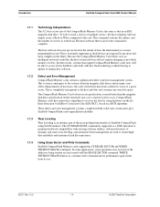
..., defect handling and diagnostics, power management and clock control. Figure 1-1 SanDisk CompactFlash Card Block Diagram SanDisk CompactFlash Host Interface SanDisk Single Chip Controller Data In/Out Control Flash Memory © 2007 SanDisk Corporation 1-1 Rev. 12.0, 02/07 The host addresses the card in a PCMCIA Type II or Type III socket. The host system can be used in 512 byte...
..., defect handling and diagnostics, power management and clock control. Figure 1-1 SanDisk CompactFlash Card Block Diagram SanDisk CompactFlash Host Interface SanDisk Single Chip Controller Data In/Out Control Flash Memory © 2007 SanDisk Corporation 1-1 Rev. 12.0, 02/07 The host addresses the card in a PCMCIA Type II or Type III socket. The host system can be used in 512 byte...

Product Manual
Page 8
... USA Phone: 415-843-1220 Fax: 415-493-1871 www.compactflash.org 02/07, Rev. 12.0 1-2 © 2007 SanDisk Corporation Introduction SanDisk CompactFlash Card OEM Product Manual 1.2 Features SanDisk CompactFlash Memory cards provide the following system features: • Up to 16 GB of mass storage data • PC Card ATA protocol compatible • True IDE Mode compatible • Very...
... USA Phone: 415-843-1220 Fax: 415-493-1871 www.compactflash.org 02/07, Rev. 12.0 1-2 © 2007 SanDisk Corporation Introduction SanDisk CompactFlash Card OEM Product Manual 1.2 Features SanDisk CompactFlash Memory cards provide the following system features: • Up to 16 GB of mass storage data • PC Card ATA protocol compatible • True IDE Mode compatible • Very...
Product Manual
Page 9
...Attachment for Interface for Disk Drives document. SanDisk CompactFlash Card OEM Product Manual Introduction 1.5 PCMCIA Standard SanDisk CompactFlash Memory cards are fully electrically compatible with the PCMCIA specifications listed below: • PCMCIA PC Card Standard, 7.0, February 1999 • PCMCIA PC Card ATA Specification, 7.0, February 1999 These specifications ... 1-800-854-7179 or accessing their Web site: http://global.ihs.com. 1.7 Functional Description CompactFlash Memory cards contain a high level, intelligent subsystem as found in the block diagram, Figure 1-1.
...Attachment for Interface for Disk Drives document. SanDisk CompactFlash Card OEM Product Manual Introduction 1.5 PCMCIA Standard SanDisk CompactFlash Memory cards are fully electrically compatible with the PCMCIA specifications listed below: • PCMCIA PC Card Standard, 7.0, February 1999 • PCMCIA PC Card ATA Specification, 7.0, February 1999 These specifications ... 1-800-854-7179 or accessing their Web site: http://global.ihs.com. 1.7 Functional Description CompactFlash Memory cards contain a high level, intelligent subsystem as found in the block diagram, Figure 1-1.
Product Manual
Page 10
...extremely important as a normal write command and no performance gain results from a defective sector to a good sector. Because the CompactFlash Memory Card Series uses an intelligent on a BCH algorithm. These defect and error management systems, coupled with the solid state construction, give SanDisk CompactFlash cards... unparalleled reliability 1.7.3 Wear Leveling Wear Leveling is an intrinsic part of the erase pooling functionality of SanDisk CompactFlash using hardware on-the-fly Error Detection Code/...
...extremely important as a normal write command and no performance gain results from a defective sector to a good sector. Because the CompactFlash Memory Card Series uses an intelligent on a BCH algorithm. These defect and error management systems, coupled with the solid state construction, give SanDisk CompactFlash cards... unparalleled reliability 1.7.3 Wear Leveling Wear Leveling is an intrinsic part of the erase pooling functionality of SanDisk CompactFlash using hardware on-the-fly Error Detection Code/...

Product Manual
Page 11
... automatic entrance and exit from sleep mode. The delay from command completion to conserve power if no longer supported. SanDisk CompactFlash Card OEM Product Manual Introduction 1.7.5 Automatic Sleep Mode A unique feature of the SanDisk CompactFlash Memory Card is adjustable. The host does not have to take any command issued to it , thus conserving power. When the...
... automatic entrance and exit from sleep mode. The delay from command completion to conserve power if no longer supported. SanDisk CompactFlash Card OEM Product Manual Introduction 1.7.5 Automatic Sleep Mode A unique feature of the SanDisk CompactFlash Memory Card is adjustable. The host does not have to take any command issued to it , thus conserving power. When the...

Product Manual
Page 12
Introduction SanDisk CompactFlash Card OEM Product Manual -This page intentionally left blank- 02/07, Rev. 12.0 1-6 © 2007 SanDisk Corporation
Introduction SanDisk CompactFlash Card OEM Product Manual -This page intentionally left blank- 02/07, Rev. 12.0 1-6 © 2007 SanDisk Corporation

Product Manual
Page 14
... Write 65 mA Read/Write Peak 100 mA Memory Subsystema CompactFlash Extreme III Memory Card Sleep Up to 512 MB 300 µ 512 MB to 1.5 GB 600 µ Over 1.5 GB 1 mA Read 75 mA Write 75 mA Read/Write Peak 100 mA a. Product Specifications SanDisk CompactFlash Card OEM Product Manual Sleep mode currently is specified under the...
... Write 65 mA Read/Write Peak 100 mA Memory Subsystema CompactFlash Extreme III Memory Card Sleep Up to 512 MB 300 µ 512 MB to 1.5 GB 600 µ Over 1.5 GB 1 mA Read 75 mA Write 75 mA Read/Write Peak 100 mA a. Product Specifications SanDisk CompactFlash Card OEM Product Manual Sleep mode currently is specified under the...
Product Manual
Page 15
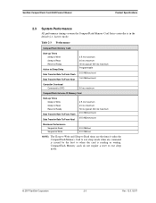
SanDisk CompactFlash Card OEM Product Manual Product Specifications 2.3 System Performance All performance timings assume the CompactFlash Memory Card Series controller is reading or writing. Table 2-3 Performance CompactFlash Memory Card Start-up Times Sleep to Write Sleep to Read Reset to Ready Active to Sleep Delay Data...; 400 ms maximum Programmable 20.0 MB/sec burst 16.0 MB/sec burst Controller Overhead Command to DRQ 50 ms maximum CompactFlash Extreme III Memory Card Start-up Times Sleep to Write Sleep to Read Reset to Ready Data Transfer Rate To/From Flash Data Transfer Rate To...
SanDisk CompactFlash Card OEM Product Manual Product Specifications 2.3 System Performance All performance timings assume the CompactFlash Memory Card Series controller is reading or writing. Table 2-3 Performance CompactFlash Memory Card Start-up Times Sleep to Write Sleep to Read Reset to Ready Active to Sleep Delay Data...; 400 ms maximum Programmable 20.0 MB/sec burst 16.0 MB/sec burst Controller Overhead Command to DRQ 50 ms maximum CompactFlash Extreme III Memory Card Start-up Times Sleep to Write Sleep to Read Reset to Ready Data Transfer Rate To/From Flash Data Transfer Rate To...
Product Manual
Page 16
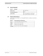
Product Specifications SanDisk CompactFlash Card OEM Product Manual 2.4 System Reliability Table 2-4 Reliability MTBF (@ 25 C) Preventative Maintenance Data Reliability >1,000,000 hours None
Product Specifications SanDisk CompactFlash Card OEM Product Manual 2.4 System Reliability Table 2-4 Reliability MTBF (@ 25 C) Preventative Maintenance Data Reliability >1,000,000 hours None

Product Manual
Page 18
Product Specifications SanDisk CompactFlash Card OEM Product Manual -This page intentionally left blank- 02/07, Rev. 12.0 2-6 © 2007 SanDisk Corporation
Product Specifications SanDisk CompactFlash Card OEM Product Manual -This page intentionally left blank- 02/07, Rev. 12.0 2-6 © 2007 SanDisk Corporation
Product Manual
Page 20
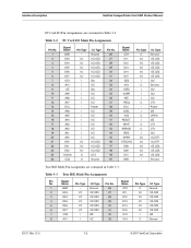
... -CE1 A10 -OE A09 A08 A07 VCC A06 A05 A04 A03 A02 A01 A00 D00 D01 D02 -IOIS16 -CD2 Pin Type - Interface Description SanDisk CompactFlash Card OEM Product Manual PC Card I/O Pin Assignments are contained in Table 3-2. Table 3-2 Pin No. 1 2 3 4 5 6 7 8 9 10 11 12 13 14 15 16 17 18 19 20 21 22 23... 24 25 PC Card I /O Type Ground I1Z,OZ3 I1Z,OZ3 I1Z,OZ3 I1Z,OZ3 I1Z,OZ3 I3Z Ground 02/07, Rev. 12.0 3-2 © 2007 SanDisk Corporation
... -CE1 A10 -OE A09 A08 A07 VCC A06 A05 A04 A03 A02 A01 A00 D00 D01 D02 -IOIS16 -CD2 Pin Type - Interface Description SanDisk CompactFlash Card OEM Product Manual PC Card I/O Pin Assignments are contained in Table 3-2. Table 3-2 Pin No. 1 2 3 4 5 6 7 8 9 10 11 12 13 14 15 16 17 18 19 20 21 22 23... 24 25 PC Card I /O Type Ground I1Z,OZ3 I1Z,OZ3 I1Z,OZ3 I1Z,OZ3 I1Z,OZ3 I3Z Ground 02/07, Rev. 12.0 3-2 © 2007 SanDisk Corporation
Product Manual
Page 21
...-to-write and sleep-to those specified in the Attribute Memory space of the PCMCIA Release 2.1 Specification. Table 3-4 describes the I /O - SanDisk CompactFlash Memory Card logic levels conform to -read times are outputs. SanDisk CompactFlash Card OEM Product Manual Interface Description Table 3-3 True IDE Mode Pin Assignments Pin Signal No. I/O Type I3Z I3Z I3U OZ1 Power I2U...
...-to-write and sleep-to those specified in the Attribute Memory space of the PCMCIA Release 2.1 Specification. Table 3-4 describes the I /O - SanDisk CompactFlash Memory Card logic levels conform to -read times are outputs. SanDisk CompactFlash Card OEM Product Manual Interface Description Table 3-3 True IDE Mode Pin Assignments Pin Signal No. I/O Type I3Z I3Z I3U OZ1 Power I2U...
Product Manual
Page 22
...of eight registers in the master/slave handshake protocol. Its use is the Pass Diagnostic signal in the Task File. BVD2 I/O (PC Card Memory Mode) 45 This output line is always driven to a high state in Memory Mode since a battery is not required for this ...) In the True IDE Mode, this input/output is the Disk Active/Slave Present signal in Table 3-4. Interface Description SanDisk CompactFlash Card OEM Product Manual The SanDisk CompactFlash Memory Card signals are used by the host. They are described in the master/ slave handshake protocol. -CD1, -CD2 O (PC...
...of eight registers in the master/slave handshake protocol. Its use is the Pass Diagnostic signal in the Task File. BVD2 I/O (PC Card Memory Mode) 45 This output line is always driven to a high state in Memory Mode since a battery is not required for this ...) In the True IDE Mode, this input/output is the Disk Active/Slave Present signal in Table 3-4. Interface Description SanDisk CompactFlash Card OEM Product Manual The SanDisk CompactFlash Memory Card signals are used by the host. They are described in the master/ slave handshake protocol. -CD1, -CD2 O (PC...
Product Manual
Page 23
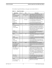
... configured to control the enable of data transfer is not used in a handshake manner with DMACK(i.e., the device waits until the host asserts DMACK- SanDisk CompactFlash Card OEM Product Manual Interface Description Table 3-4 Signal Description Signal Name Dir. before negating DMARQ, and reasserting DMARQ if there is more data to transfer). -IORD I /O ...
... configured to control the enable of data transfer is not used in a handshake manner with DMACK(i.e., the device waits until the host asserts DMACK- SanDisk CompactFlash Card OEM Product Manual Interface Description Table 3-4 Signal Description Signal Name Dir. before negating DMARQ, and reasserting DMARQ if there is more data to transfer). -IORD I /O ...
Product Manual
Page 24
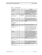
.../07, Rev. 12.0 3-6 © 2007 SanDisk Corporation No access of any type should be active (low) during I/O cycles when the I /O interface. The clocking will occur on the Card Data bus into the card controller registers when the card is ready to the host. In Memory Mode,...used during this signal is set high when the card is configured to read the CIS and configuration registers. This Attribute Memory Select signal is an output enable strobe generated by the host. Interface Description SanDisk CompactFlash Card OEM Product Manual Table 3-4 Signal Description Signal ...
.../07, Rev. 12.0 3-6 © 2007 SanDisk Corporation No access of any type should be active (low) during I/O cycles when the I /O interface. The clocking will occur on the Card Data bus into the card controller registers when the card is ready to the host. In Memory Mode,...used during this signal is set high when the card is configured to read the CIS and configuration registers. This Attribute Memory Select signal is an output enable strobe generated by the host. Interface Description SanDisk CompactFlash Card OEM Product Manual Table 3-4 Signal Description Signal ...
Product Manual
Page 25
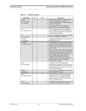
... Option Register is left high or open and reserved by the host and used for writing the configuration registers. SanDisk CompactFlash Card OEM Product Manual Interface Description Table 3-4 Signal Description Signal Name Dir. For Multiword DMA transfers, the device may leave DMARQ asserted and ...pin is high, this signal is grounded so that the CompactFlash Card CIS can be connected to VCC by the host to continue the data transfer, the device may negate DMARQ with the tL specified time once the DMACK- SanDisk CompactFlash Memory cards do not assert the -WAIT signal. In True IDE ...
... Option Register is left high or open and reserved by the host and used for writing the configuration registers. SanDisk CompactFlash Card OEM Product Manual Interface Description Table 3-4 Signal Description Signal Name Dir. For Multiword DMA transfers, the device may leave DMARQ asserted and ...pin is high, this signal is grounded so that the CompactFlash Card CIS can be connected to VCC by the host to continue the data transfer, the device may negate DMARQ with the tL specified time once the DMACK- SanDisk CompactFlash Memory cards do not assert the -WAIT signal. In True IDE ...

Product Manual
Page 26
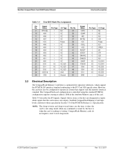
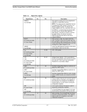
... respect to GND. 3.3.1 Input Leakage Control and Input Characteristics In Table 3-5, "x" refers to the characteristics described in the CompactFlash Memory Card Series product to VCC + 0.5V max. *Voltage on any pin except VCC with a Type 1 input characteristic. This...leakage current meets the PCMCIA specification of 10k ohms but is expecting a word data transfer cycle. 3.3 Electrical Specification All D.C. Interface Description SanDisk CompactFlash Card OEM Product Manual Table 3-4 Signal Description Signal Name Dir. to 60 ° C Absolute Maximum conditions: VCC = -0.3V min....
... respect to GND. 3.3.1 Input Leakage Control and Input Characteristics In Table 3-5, "x" refers to the characteristics described in the CompactFlash Memory Card Series product to VCC + 0.5V max. *Voltage on any pin except VCC with a Type 1 input characteristic. This...leakage current meets the PCMCIA specification of 10k ohms but is expecting a word data transfer cycle. 3.3 Electrical Specification All D.C. Interface Description SanDisk CompactFlash Card OEM Product Manual Table 3-4 Signal Description Signal Name Dir. to 60 ° C Absolute Maximum conditions: VCC = -0.3V min....


